
 WhatsApp: +86 16626708626
 Email:
  Phone: +86 16626708626
Description
Key Technical Specifications
| Parameter | Specification |
|---|---|
| Manufacturer | FANUC |
| Part Number | A20B-8101-0420 |
| Series | A20B-8101 |
| Product Type | Line tracking PCB / interface board |
| Function | Line tracking signal interface and processing |
| Related Codes | C0P10A, C0P10B |
| Associated Connectors | JF21, JF22 |
| Application | FANUC robot / industrial control systems |
| Board Category | FANUC PCB |
| Manufacturer Status | Discontinued |
| Typical Replacement Condition | New old stock, used, refurbished |
| Configuration | Machine/controller dependent |
FANUC’s public spare-parts information available for this exact number is limited. The strongest consistent identification across independent parts sources is Line Tracking PCB / Line Track Interface Board. MRO Electric, for example, lists A20B-8101-0420 as a LINE TRACK INTERFACE BOARD, while FanucWorld and Robots.com identify it as a LINE TRACKING PCB.
A supplier listing also identifies C0P10A, C0P10B, JF21, and JF22 with the part number. These identifiers are useful when comparing an installed board, but they should not be treated as proof that every machine using those markings is interchangeable.
Product Introduction
The FANUC A20B-8101-0420 is a legacy FANUC line tracking interface PCB used to support line-tracking functions in compatible robot or industrial control configurations. It provides the electronic interface associated with the line-tracking system rather than serving as the robot controller’s main CPU or servo amplifier.
This distinction matters during replacement. The A20B-8101-0420 should be matched against the original board number, controller configuration, connector arrangement, and line-tracking hardware. The part is listed as discontinued by the manufacturer, so procurement typically involves new old stock, used, or refurbished inventory.
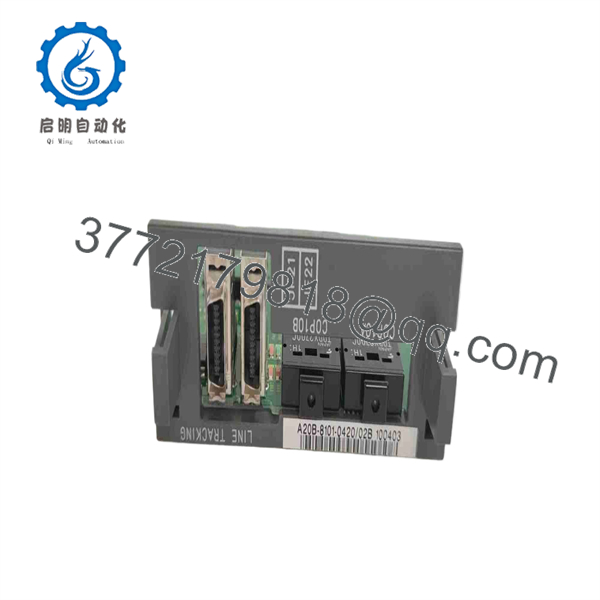
A20B-8101-0420
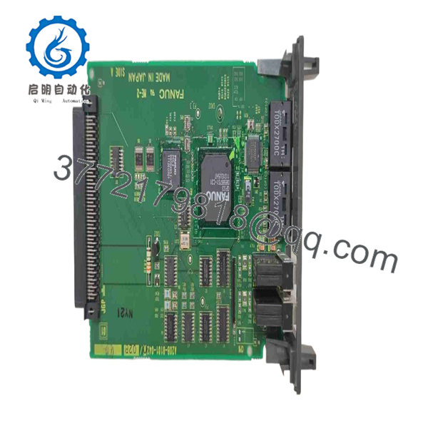
A20B-8101-0420
Installation & Configuration Guide
Stage 1 — Pre-Installation Preparation
- Record the complete board number from the installed PCB: A20B-8101-0420.
- Photograph the board label, connectors, cable routing, and mounting position.
- Record the FANUC robot controller model and software/configuration information.
- Shut down the robot using the normal controller procedure.
- Apply lockout/tagout (LOTO) to the relevant machine power sources.
- Wait at least 5 minutes after power removal before opening the cabinet.
- Verify that hazardous voltage has been removed.
- Use ESD protection when handling the PCB.
- Retain the original board until the replacement has completed commissioning.
Because line-tracking boards are configuration-dependent, photographs of the original board and connector locations are particularly useful when sourcing a discontinued replacement.
Stage 2 — Removing the Existing PCB
- Confirm that controller power is isolated.
- Open the appropriate FANUC cabinet or controller access area.
- Locate the existing A20B-8101-0420.
- Confirm the board identification before disconnecting anything.
- Label cables and connectors.
- Photograph the JF21/JF22 area if those connectors are present.
- Disconnect the associated cables without pulling on the conductors.
- Release the PCB mounting hardware.
- Remove the board using ESD precautions.
- Inspect the connectors and surrounding wiring for oxidation, bent pins, loose terminals, or physical damage.
JF21 and JF22 are specifically associated with this part number in aftermarket technical listings.
Stage 3 — Installing the Replacement
- Confirm the replacement marking is .
- Compare PCB revision markings and connector layout with the removed board.
- Inspect the replacement for corrosion, cracked components, damaged connectors, or contamination.
- Install the PCB in the original mounting position.
- Reconnect each cable to its original connector.
- Verify that JF21/JF22 connections, where applicable, match the original configuration.
- Do not add jumpers, change wiring, or alter factory settings unless the applicable FANUC documentation explicitly requires it.
- Check that all connectors are fully seated.
- Confirm that cables are routed without mechanical strain.
- Complete a final visual inspection before closing the cabinet.
Important compatibility warning
Do not substitute solely because another FANUC board looks physically similar. The family contains multiple specialized boards, including line-tracking, automation, CC-Link, and Ethernet-related boards. MRO Electric’s catalog, for eists as a line-track interface board while -0550 and -0770 perform different functions.
Stage 4 — Power-On & Testing
After installation:
- Verify controller grounding and cabinet wiring.
- Confirm that no tools or foreign objects remain inside the cabinet.
- Reapply power under controlled conditions.
- Check the controller display and alarm history.
- Verify that no line-tracking-related alarms appear.
- Confirm the line-tracking device/interface is recognized correctly.
- Check the tracking signal while the conveyor or moving workpiece is stationary.
- Perform a controlled low-speed tracking test.
- Verify robot position correction or tracking response.
- Run a production-equivalent dry cycle before releasing the machine.
Troubleshooting sequence
If line tracking does not operate after replacement, check:
- Exact board number and revision
- Connector seating
- JF21/JF22 wiring where applicable
- External line-tracking sensor or encoder
- Controller configuration
- Tracking-related parameters
- Cable continuity
- Existing sensor/encoder faults
- Controller alarm history
Do not condemn the replacement PCB until the external tracking device and associated wiring have been checked.
Frequently Asked Questions
Q1. ANUC ?
It is a FANUC line tracking PCB / line track interface board used in compatible FANUC robot and industrial control systems.
Q2. What are C0P10A and C0P10B?
C0P10A and C0P10B are identifiers aswith in industrial spare-parts listings. They can help with identification when comparing the original board, but they should not be used by themselves to establish machine compatibility.
Q3. What are and ?
and are connector identifiers associ the line-tracking board in available product documentation and replacement listings. The actual connector usage depends on the original FANUC system configuration.
Q4. Is a servo amplifier?
No. The most consistent exact-part identification describes it as a line tracking PCB/interface board. One repair-site category incorrectly places the number under servo amplifiers/inverters, but that conflicts with the more specific exact-part descriptions from multiple sources.
. Is discontinued?
Yes. Radwell explicitly lists it as discontinued by manufacturer, and REACO CNC also identifies it as discontinued. Existing inventory can still be found as new old stock, used, or refurbished equipment.
Can be replacB-8101-0421?
Do not assume so. -0421 is separately listed as a line tracking PCB, but the existence of adjacent part numbers does not establish electrical or firmware compatibility. The controller model, original board revision, connectors, and line-tracking configuration should be checked before substitution.
Q7. What should be checked before purchasing a replacement?
For a discontinued FANUC board, verify:
- Complete part number:
- Any revision or suffix, such as /02B
- FANUC controller model
- Robot model and line-tracking configuration
- PCB label and connector layout
- / configuration where applicable
- Condition: new old stock, used, refurbished, or repaired
- Functional test documentation
- Warranty and return terms
A supplier listing specifically shows an variant, demonstrating why the complete marking on the installed board should be captured before ordering.



