
 WhatsApp: +86 16626708626
 Email:
  Phone: +86 16626708626
Description
Key Technical Specifications
| Parameter | Value |
| Manufacturer | Foxboro / Schneider Electric |
| Part Number | E69F-BI2-S |
Enclosure Type (B) |
Bolted Cover, Weatherproof (NEMA Type 4 / IEC IP65) |
Input Signal Range (I) |
4 to 20 mA DC (170 Ω input impedance, Direct/Reverse Action) |
Output Signal Range (2) |
20 to 100 kPa / 3 to 15 psi / 0.2 to 1.0 bar |
Integral Option (-S) |
Supply and Output Pressure Indicating Gauges Included |
| Pneumatic Connections | 1/4 inch NPT (Air Supply and Output Signal) |
| Electrical Connection | 1/2 inch NPT Conduit Tap with 18 AWG Twisted Leads |
| Supply Pressure Requirement | 140 kPa / 20 psi recommended for 3–15 psi output |
| Operating Temperature | 0 to +60 °C (32 to 140 °F) normal; −40 to +80 °C ambient limits |
| Construction Material | Die-cast low-copper aluminum alloy with epoxy powder finish |
| Approximate Weight | 5.0 lbs (2.3 kg) |
Product Introduction & Supply Chain Strategy
The Foxboro E69F-BI2-S is a rugged, field-mounted current-to-pneumatic (I/P) transducer engineered to translate 4–20 mA control signals from DCS, PLC, or single-loop controllers into a precise 3–15 psi pneumatic output. Designed specifically to drive control valve positioners, dampers, and pneumatic actuators, the unit utilizes a galvanometric motor with generous coil-to-housing clearances, ensuring minimal susceptibility to ambient vibration, atmospheric changes, and airborne dust.
Holding the E69F-BI2-S as New Surplus provides immediate protection against control loop downtime on critical process lines. Because reconditioned or third-party repaired I/P converters often suffer from worn internal flexures, clogged flapper-nozzle relays, or aged motor magnets that drift under thermal stress, procuring a factory-sealed unit ensures factory-calibrated accuracy and OEM-level repeatability. Installing genuine New Surplus avoids the risk of valve hunting or position drift, yielding a significantly lower Total Cost of Ownership (TCO) over the instrument’s operational life.
Installation & Configuration Guide
1.Stage 1: Pre-Installation (Prep & Safety):Prerequisite & Safety Isolation.
Isolate the 4–20 mA loop feed from the control system and isolate the pneumatic instrument air supply line. Put on a grounded ESD wrist strap. Clean instrument air (free of oil, moisture, and dust per ISA 7.0.01 standards) must be verified before connecting pneumatic lines.
2.Stage 2: Removal:Mechanical Extraction.
Disconnect the 1/2-inch electrical conduit fitting and disconnect the twisted wire leads. Relieve air pressure in the supply line and unscrew the 1/4-inch NPT supply and output pneumatic fittings. Loosen the U-bolt pipe mount clamps and lift the existing unit off its vertical 2-inch pipe stand or valve yoke.
3.Stage 3: Installation (Clone & Seat):Hardware Mounting.
Inspect the New Surplus E69F-BI2-S for intact factory seals and pristine port threads. Mount the unit vertically onto the 2-inch pipe stand or valve yoke using the original mounting bracket. Apply PTFE thread sealant (tape or paste) sparingly to male 1/4-inch NPT air fittings—ensuring no tape fragments enter the internal pneumatic ports—and make all pneumatic connections. Connect the 4–20 mA loop leads to the 1/2-inch NPT conduit entry.
4.Stage 4: Power-On & Testing:Calibration & Verification.
Supply 20 psi (140 kPa) of clean instrument air and observe the supply pressure gauge (-S option). Apply a 4 mA DC input signal and verify the output gauge reads 3 psi (20 kPa); adjust the internal zero screw if minor offset exists. Increase the loop signal to 20 mA DC and confirm the output gauge reads 15 psi (100 kPa), verifying smooth linear progression across the entire 4–20 mA range without output hysteresis.
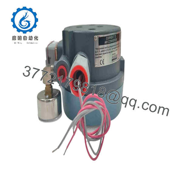
E69F-BI2-S
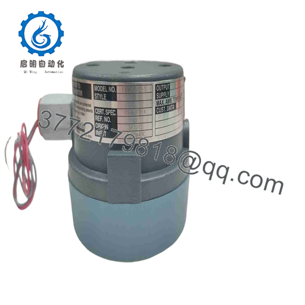
E69F-BI2-S
Firmware/Software Versions & Upgrade Notes
- Pure Hardware Device: The E69F-BI2-S is an analog electromechanical transducer and does not contain firmware, microprocessors, or digital bus protocols.
- Direct vs. Reverse Action Settings: The unit is factory-calibrated for direct action (4 mA = 3 psi, 20 mA = 15 psi). If your process requires reverse action (4 mA = 15 psi, 20 mA = 3 psi), the internal galvanometric motor linkages must be mechanically repositioned according to Foxboro MI 018-430 guidelines.
- Pneumatic Relay Maintenance: The integral pneumatic relay (Foxboro Part Number 31-07-009) contains an internal restrictor. Always verify air cleanliness; oil or moisture contamination in the air line will require relay removal and cleaning.
Frequently Asked Questions (FAQ)
Q: What does the “BI2-S” breakdown mean in the Foxboro model code? A: In the E69F model breakdown: B = Weatherproof Bolted Cover Enclosure, I = 4–20 mA DC Input (170 Ω impedance), 2 = 3–15 psi (20–100 kPa) Pneumatic Output, and -S = Integral Supply and Output Pressure Gauges.
Q: Is this unit brand new or refurbished? A: This product is 100% Brand New Surplus in original OEM condition. It has never been installed in an operating plant, pulled from a decommissioned skid, or rebuilt with non-OEM parts.
Q: Can the E69F-BI2-S be used in hazardous or explosionproof locations? A: No. The B option indicates a weatherproof bolted cover enclosure meant for non-explosionproof applications. For explosionproof/flameproof installations, Foxboro requires the threaded cover housing option (designated as E69F-T…).
Q: Do I need an external filter regulator with this unit? A: An upstream filter regulator (such as the optional Foxboro -R selection or a standard Airset) is recommended to regulate plant air down to the required 20 psi supply and ensure the instrument receives clean, dry air.
Q: What warranty is included with this New Surplus transducer? A: We provide a full 1-year functional replacement warranty on all New Surplus Foxboro field instruments.



