
 WhatsApp: +86 16626708626
 Email:
  Phone: +86 16626708626
Description
Key Technical Specifications
| Parameter | Specification |
|---|---|
| Model | E69F-BI2 |
| Manufacturer | Foxboro |
| Product Series | E69F |
| Product Type | Field-mounted current-to-pneumatic converter |
| Conversion | Electrical current → pneumatic pressure |
| Input Signal | 4–20 mA DC |
| Alternate Input Ranges | 4–12 mA DC or 12–20 mA DC |
| Input Impedance | 170 Ω |
| Output Signal | 20–100 kPa |
| Equivalent Output | 3–15 psi |
| Alternate Output | 0.2–1.0 bar or kg/cm² |
| Action | Direct or reverse action |
| Enclosure | Bolted cover, weatherproof |
| Typical Weight | 2.3 kg |
| Shipping Weight | Approximately 4–4.5 kg |
| Mounting | Field-mounted |
| Current Status | Discontinued / obsolete |
The E69F ordering information confirms the B enclosure code, I input configuration, and 2 output configuration. The standard BI2 configuration accepts 4–20 mA and produces 20–100 kPa / 3–15 psi.
Specification caution: Several reseller pages currently associate incorrect electrical specifications with E69F-BI2, including 24 VDC power supply and 0–10 V output. Those specifications conflict with the E69F ordering information and should not be used for replacement selection.
Product Introduction
The Foxboro E69F-BI2 is a field-mounted current-to-pneumatic I/P converter used to translate a 4–20 mA DC control signal into proportional pneumatic pressure. Its standard BI2 configuration provides a 20–100 kPa (3–15 psi) output for pneumatic control applications.
The important replacement issue is configuration matching. The family includes different input/output ranges, enclosure options, and application suffixes. The exact nameplate and ordering code should therefore be checked before substitution. The -BI2 has been discontinued, and suppliers identify the Foxboro IP26-1000 series as a replacement family.
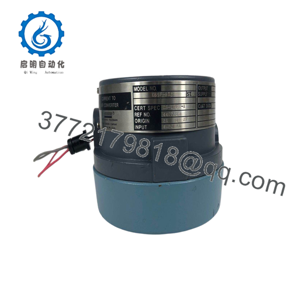
E69F-BI2
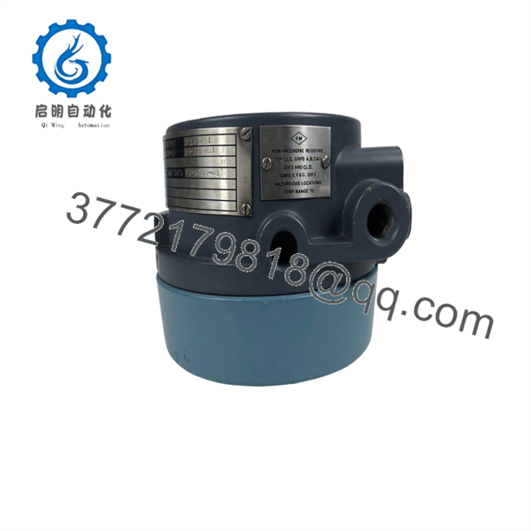
E69F-BI2
Installation & Configuration Guide
Stage 1: Pre-Installation Preparation — 10 minutes
⚠️ Safety First: Put the process in a safe operating state before removing the converter. Isolate the electrical loop as required by the plant’s LOTO procedure and isolate/depressurize the pneumatic supply before disconnecting air tubing.
Tools Required:
- Multimeter capable of measuring 4–20 mA
- Calibrated pressure gauge
- Appropriate screwdriver/wrench set
- Tubing labels
- Wire labels
- Camera or smartphone
- Calibrated current source, if available
Before removal:
- Photograph the complete -BI2 installation.
- Photograph the model/nameplate and certification markings.
- Record the existing input wiring polarity.
- Record pneumatic supply and output tubing connections.
- Record whether the existing converter is configured for direct or reverse action.
- Record the output pressure range.
- Confirm that the replacement is , not a superficially similar variant.
⚠️ The family contains multiple configurations. Do not order solely from the “” prefix.
Stage 2: Removing the Old Converter — 5–10 minutes
- Isolate the 4–20 mA loop.
- Shut off the instrument-air supply.
- Bleed residual pneumatic pressure safely.
- Label each electrical conductor.
- Disconnect the current-loop wiring.
- Label and disconnect the pneumatic tubing.
- Remove the field-mounting hardware.
- Inspect the tubing for contamination, moisture, or damaged fittings.
- Keep the old converter available for comparison during commissioning.
⚠️ Do not apply uncontrolled instrument air directly to the output connection. Follow the applicable installation and calibration procedure.
Stage 3: Installing the -BI2 — 10–15 minutes
- Verify the complete model designation on the replacement.
- Confirm the enclosure configuration.
- Mount the converter securely in the original field location.
- Connect the pneumatic supply and output tubing according to the installation diagram.
- Verify that tubing connections are tight and free from leakage.
- Reconnect the 4–20 mA loop with correct polarity.
- Confirm the control-system output scaling.
- Confirm whether the loop requires direct or reverse action.
Self-Checklist:
- Ex model verified
- Input range confirmed
- Output range confirmed
- Direct/reverse action confirmed
- Current-loop polarity checked
- Pneumatic tubing correctly connected
- Air leaks checked
- Mounting secured
Stage 4: Calibration & Testing — 15–30 minutes
For the standard 4–20 mA / 3–15 psi configuration:
- Apply the required instrument-air supply.
- Apply 4 mA to the converter.
- Verify the corresponding minimum pneumatic output.
- Apply 12 mA, representing 50% of the input span.
- Verify approximately 9 psi / 60 kPa at the output.
- Apply 20 mA.
- Verify approximately 15 psi / 100 kPa output.
- Check the output response at intermediate points.
- Confirm that the output moves in the expected direction.
- Return the control loop to automatic operation only after the complete signal path has been verified.
A published calibration procedure uses 12 mA → 60 kPa / 9 psi as the 50% calibration point and checks the 20 mA endpoint at 100 kPa / 15 psi. It also notes that span adjustment affects zero, so zero should be rechecked after span adjustment.
⚠️ Do not adjust zero and span repeatedly without allowing the pneumatic output to stabilize. If calibration cannot be achieved, check the current source, air supply, output restriction, tubing leakage, and the converter’s exact configuration before changing mechanical adjustments.
Frequently Asked Questions (FAQ)
Is Foxb obsolete?
Yes. Multiple industrial-parts references identify as discontinued/out of stock, while another supplier identifies the Foxboro IP26-1000 series as the replacement family.
What d convert?
The standard BI2 configuration converts a 4–20 mA DC electrical input into a 20–100 kPa (3–15 psi) pneumatic output. The documentation also lists alternative input ranges of 4–12 mA and 12–20 mA.
a control module or an I/P converter?
It is an I/P (current-to-pneumatic) converter, not a conventional DCS I/O module. Its purpose is to interface an electronic current signal with a pneumatic control element.
Can I repl directly with IP26-1000?
Not without checking the application. IP26-1000 is identified as the replacement family, but you still need to verify input range, output range, direct/reverse action, mounting, pneumatic connections, environmental requirements, and any hazardous-area requirements before making the substitution.
D require a separate electrical power supply?
Do not treat it like a conventional 24 VDC electronic module. The published ordering information specifies the 4–20 mA input circuit and 170 Ω impedance rather than the 24 VDC power specification shown on some reseller pages. Verify the loop design against the original Foxboro documentation before commissioning.
What condition should I expect when buying this obsolete model?
Because the model is discontinued, current market listings can represent different conditions: new surplus, refurbished/tested, or remaining legacy stock. The supplier should explicitly state the physical condition, serial/traceability information, packaging, and whether the unit has been function-tested. Current listings demonstrate that availability varies considerably by supplier.



