
 WhatsApp: +86 16626708626
 Email:
  Phone: +86 16626708626
Description
Key Technical Specifications
| Parameter | Value |
|---|---|
| Manufacturer | Foxboro (Schneider Electric) |
| Product Model | E69F-T12-JRS |
| Product Type | Field-Mounted Current-to-Pneumatic Converter |
| Input Signal | 4–20 mA DC (also configurable for 4–12 mA or 12–20 mA) |
| Input Impedance | 170 Ω |
| Output Signal | 3–15 psi (20–100 kPa / 0.2–1.0 bar) |
| Action | Direct or Reverse Acting |
| Enclosure | Explosion-proof threaded cover |
| Junction Box | Integral explosion-proof junction box |
| Regulator | Adjustable filter regulator (without gauge) |
| Gauges | Supply and output pressure gauges |
| Weight | Approximately 2.3 kg |
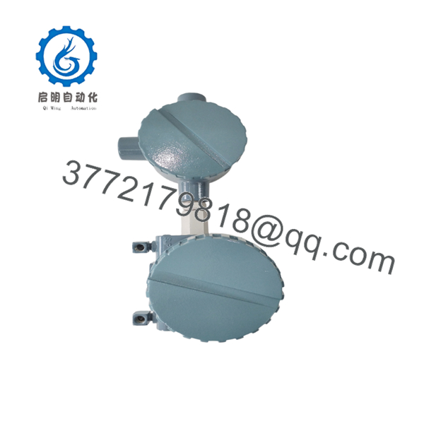
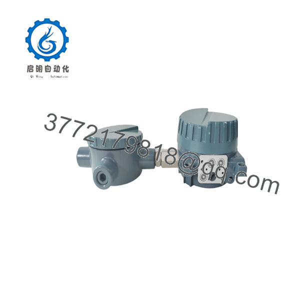
The E69F-T12-JRS is a field-mounted electro-pneumatic (I/P) converter that converts a standard DC current signal into a proportional pneumatic output for valve actuators and other pneumatic control devices.
Product Introduction
The Foxboro E69F-T12-JRS is designed for industrial process control systems that require reliable conversion of electronic controller outputs into pneumatic control signals. It is commonly installed with pneumatic control valves in refineries, chemical plants, power stations, and other continuous-process facilities.
The explosion-proof enclosure allows installation in hazardous areas when properly certified for the application. Adjustable zero and span settings simplify commissioning, while the integrated filter regulator helps maintain stable pneumatic output even when supply pressure fluctuates.
Installation & Configuration Guide
Stage 1 – Pre-Installation Preparation (10 Minutes)
⚠️ Safety First
- Isolate electrical power and instrument air.
- Depressurize the pneumatic line.
- Follow plant Lock-Out/Tag-Out procedures.
- Wear appropriate PPE when working in hazardous locations.
Required Tools
- Digital multimeter
- Pressure gauge
- Small flat-blade screwdriver
- Adjustable wrench
- Thread sealant approved for instrument air
Stage 2 – Remove Existing Converter (10 Minutes)
- Label all electrical and pneumatic connections.
- Disconnect the 4–20 mA wiring.
- Isolate and disconnect the air supply.
- Remove the converter from its mounting bracket.
⚠️ Before disposal, inspect the removed unit for contamination caused by moisture or oil in the instrument air system.
Stage 3 – Install the New Converter (15 Minutes)
- Confirm the replacement model is E69F-T12-JRS.
- Mount the converter vertically as specified by the manufacturer.
- Connect clean, dry instrument air.
- Connect the 4–20 mA input wiring.
- Verify all pneumatic fittings are leak-free.
- Adjust zero and span if required.
Installation Checklist
- ✔ Instrument air connected
- ✔ Electrical polarity verified
- ✔ No pneumatic leaks
- ✔ Output pressure calibrated
Stage 4 – Commissioning (15 Minutes)
- Apply instrument air.
- Energize the control loop.
- Inject a 4 mA signal and verify minimum output pressure.
- Apply 20 mA and verify full-scale pressure.
- Confirm smooth valve travel across the operating range.
- Record calibration values for maintenance records.
⚠️ If the output pressure is unstable, inspect the air supply quality first. Moisture, oil contamination, or insufficient supply pressure causes more field failures than the converter itself.

- E69F-T12-JRS
- E69F-T12-JRS
Frequently Asked Questions (FAQ)
Q1. What does the do?
It converts a 4–20 mA DC control signal into a proportional 3–15 psi pneumatic output, allowing electronic control systems to operate pneumatic control valves.
Q2. What does the model suffix “T12-JRS” mean?
According to the Foxboro model code:
- T – Explosion-proof threaded enclosure
- 1 – 4–20 mA input family
- 2 – 3–15 psi (20–100 kPa) output
- J – Integral explosion-proof junction box
- R – Adjustable filter regulator
- S – Supply and output pressure gauges included
Q3. Which industries commonly use this converter?
Typical applications include:
- Oil and gas production
- Petrochemical plants
- Chemical processing
- Power generation
- Water and wastewater treatment
- Pulp and paper mills
Q4. Can it operate in hazardous areas?
Yes. The T enclosure option is an explosion-proof housing intended for hazardous-area installations, provided the installation complies with applicable local electrical and hazardous-location regulations.
Q5. What air supply is required?
The converter requires clean, dry, oil-free instrument air. Contaminated air shortens regulator life, affects calibration stability, and can cause sluggish valve response.
Q6. Is recalibration required after replacement?
Usually, yes. Even when replacing the unit with the same model, verify zero and span after installation because actuator characteristics and air supply conditions vary between installations.
Q7. What should be checked before replacing the converter?
Before condemning the converter, verify:
- 4–20 mA loop current
- Instrument air pressure
- Air filter condition
- Pneumatic tubing for leaks
- Control valve actuator operation
In many field cases, the converter is not the root cause; blocked air lines or contaminated regulators are more common sources of poor valve performance.



