
 WhatsApp: +86 16626708626
 Email:
  Phone: +86 16626708626
Description
Key Technical Specifications
| Parameter | Value |
|---|---|
| Manufacturer | Foxboro, formerly Invensys Process Systems; now part of Schneider Electric |
| Module designation | FBM06 |
| Common assembly part number | P0400YG |
| Product family | Foxboro I/A Series DCS |
| Module function | Pulse input, 0–20 mA analog output interface |
| Pulse input channels | 4 configurable channels |
| Maximum input pulse rate | 12.5 kHz per input channel |
| Input resistance | 10 kΩ |
| Analog output channels | 4 isolated and independent channels |
| Output signal range | 0–20.4 mA DC per channel |
| Maximum output load | 735 Ω |
| Fieldbus supply range | 26–42 V DC via redundant fieldbus |
| Maximum power consumption | 15 W |
| Maximum heat dissipation | 12 W |
| Isolation withstand | 600 V AC for 1 minute between channels and ground, or between channels |
| Environmental classification | ISA S71.04 Class G3 harsh industrial environment |
| Typical field devices | Turbine meters, vortex meters, pulse contacts, tachometers, counters, and proportional analog actuators |
The original Foxboro product specification identifies the FBM06 as a four-channel pulse-input and four-channel 0–20 mA output interface module. Each input accepts pulse signals up to 12.5 kHz, while each output drives an external load using a 0–20.4 mA DC signal. It receives power and communications through the redundant I/A Series fieldbus.
Product Introduction
The Foxboro FBM06, commonly identified by assembly part number P0400YG, is an I/A Series DCS interface module with four pulse-input channels and four 0–20 mA analog-output channels. It connects pulse-producing field instruments—such as turbine flowmeters, vortex meters, tachometers, and contact-based totalizers—to the Foxboro control system while supplying current outputs to external analog devices.
The FBM06 is selected where a single I/A Series slot must handle pulse measurement and analog output functions. Each input and output channel is isolated, reducing ground-loop exposure between field circuits. Confirm the P0400YG assembly number, associated terminal assembly, baseplate position, and configured control strategy before ordering.
Troubleshooting Quick Reference
| Symptom | Possible Cause | Relevance to This Part | Quick Check Method | Recommendation |
|---|---|---|---|---|
| No module status indication or controller reports module absent | Fieldbus power loss, baseplate fault, poor module seating, failed FBM06 | ✅ High | Check the redundant fieldbus supply at the baseplate. The FBM06 requires 26–42 V DC through the redundant fieldbus. Inspect baseplate contacts and fully reseat the module with power isolated unless the approved maintenance procedure permits online replacement. | Restore fieldbus power and correct seating or baseplate faults before replacing the . |
| One or more pulse counts remain at zero | Open field circuit, failed sensor, missing sensor supply, incorrect input scaling, failed input channel | ⚠️ Medium | Measure the sensor pulse signal at the terminal assembly with an appropriate frequency meter or oscilloscope. Confirm the pulse frequency does not exceed 12.5 kHz. Verify field wiring continuity and sensor power separately. | Repair the sensor, wiring, or field supply first. Replace the only if a valid pulse reaches the terminal assembly but the DCS value remains incorrect. |
| Pulse count is unstable or too high | Noise pickup, shield termination error, contact bounce, damaged cable, incorrect pulse-resolution setting | ⚠️ Medium | Compare the field frequency against the DCS value. Inspect cable shielding and grounding against the plant wiring standard. For dry contacts, check for bounce using a scope or a high-speed counter. | Correct shielding, grounding, and sensor conditioning before adjusting software parameters or replacing hardware. |
| Output stays at 0 mA | Control strategy is commanding zero, output loop is open, field wiring is reversed, output channel failure | ⚠️ Medium | Place the loop in a controlled test condition under site approval. Measure output current in series at the terminal assembly and compare it with the DCS output command. | If the DCS command is correct but no current is present at the terminal, isolate the output loop and verify wiring before replacing the . |
| Output is commanded but control valve does not move | Failed valve positioner, loss of loop power, open field cable, incorrect output range, excessive loop load | ❌ Low | Measure loop current at the output and at the valve positioner. Check loop resistance against the 735 Ω maximum output-load limit. Verify that the positioner accepts 0–20 mA rather than only 4–20 mA. | Diagnose the field loop and positioner first. A healthy can produce current while the final element remains unresponsive. |
| Output current is inaccurate | Incorrect engineering scaling, failed loop calibration, excessive load, poor common reference, damaged output circuit | ⚠️ Medium | Command known values such as 0%, 25%, 50%, 75%, and 100%. Measure the loop current with a calibrated meter and compare with DCS engineering units. | Confirm the configured scaling and field-device calibration before replacing the module. |
| Multiple channels fail after a cabinet event | Loss of redundant fieldbus, common terminal assembly issue, surge event, cabinet grounding problem | ✅ High | Check both fieldbus legs, baseplate condition, cabinet ground bonding, and terminal assembly connections. Inspect for heat marks or surge damage. | Investigate the common cause before installing a replacement. Do not put a new into a cabinet with an unresolved power or grounding fault. |
| Module faults after replacement | Wrong FBM type, incompatible terminal assembly, field wiring transferred incorrectly, configuration not restored, ESD damage | ✅ High | Compare the removed unit and replacement label: and P0400YG. Photograph field terminals, verify terminal assembly part number, and confirm the DCS database identifies the slot as . | Do not wire from memory. Restore the correct module configuration and use ESD controls during handling. |
Field note: A pulse-input fault is often a field-instrument or shield problem, not an failure. I have seen technicians replace the module only to find a cracked turbine-meter pickup cable inside a junction box. Verify the real pulse signal at the terminal assembly before pulling the card.
For support, provide a photo of the front label, P0400YG marking, terminal assembly, baseplate slot, module status LEDs, DCS diagnostics, pulse-frequency measurement, and current-loop readings.
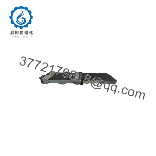
FBM06
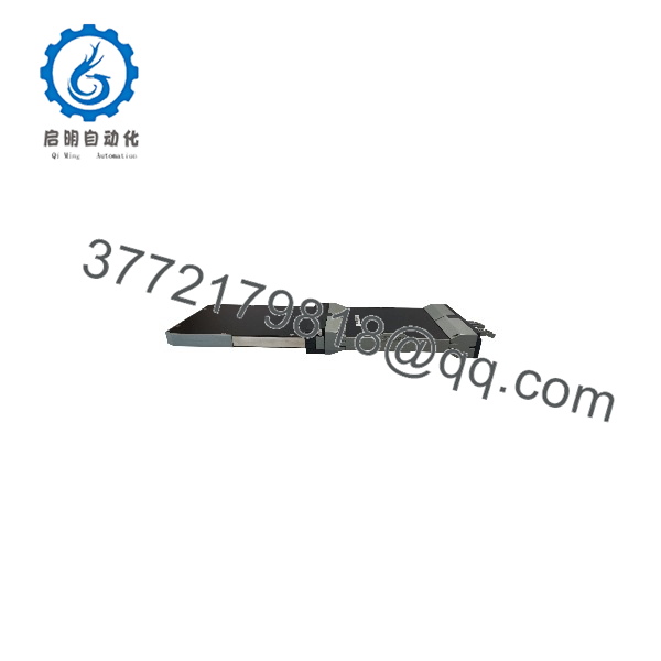
FBM06
Frequently Asked Questions
Is the Foxboro the same as P0400YG?
In normal Foxboro I/A Series spare-parts usage, is commonly associated with the module assembly. Still, verify the exact label on the unit being replaced. Legacy Foxboro parts can have related identifiers for the module, terminal assembly, baseplate, revision, and packaging, so an exact label photograph is better than relying on a short description.
How many inputs and outputs does the have?
The has four configurable pulse-input channels and four 0–20 mA DC analog-output channels. The pulse inputs support a maximum signal rate of 12.5 kHz. Each output can produce up to 20.4 mA DC and can drive a load up to 735 Ω.
Can I use the for a 4–20 mA input signal?
No. The is not a general-purpose 4–20 mA analog-input card. Its four input channels are intended for pulse/frequency signals. It can generate 0–20 mA analog outputs, which may be engineered for a 4–20 mA operating span in the control strategy if the connected field device and site configuration support it. Do not connect a transmitter’s 4–20 mA output to a pulse-input channel.
Can I hot-swap an ?
Follow the approved plant procedure and the applicable I/A Series maintenance documentation. The module is part of a redundant fieldbus architecture, but that does not give permission to remove it casually from an energized process cabinet. Confirm process impact, force or bypass outputs only under authorized control, use an ESD wrist strap, and make sure the replacement unit matches the installed assembly before removal.
A 3:00 AM rule: if the controls a live valve, do not pull it until you know what the output will do on fault. Check the configured fail-safe response first.
What is the maximum frequency input for the ?
The documented maximum pulse-input rate is 12.5 kHz per channel. If the field device produces more than 12,500 pulses per second at full process range, the input will not be suitable without changing the meter factor, adding signal conditioning, or selecting a different I/O solution.
Why is my output reading 0 mA when the DCS commands an output?
Start with the external loop. Check whether the DCS strategy is actually issuing a nonzero command, whether the output channel is inhibited or faulted, whether the loop wiring is open, whether the polarity is correct, and whether the total loop resistance stays below 735 Ω. Then measure current directly at the terminal assembly.
Do not assume the module is bad because the valve is not moving. The can be producing the correct current while the positioner has lost loop power, has a failed input circuit, or is mechanically stuck.
Is this module New Surplus or Refurbished?
The offered condition must be explicit. New Original / New Surplus means unused legacy inventory with original identity labels and documented storage condition. Refurbished (tested) means a used module that has been inspected and functionally verified.
For a refurbished , request the actual-unit photos, label photo, fieldbus power-on result, DCS or bench communication test, pulse-input simulation at multiple frequencies, 0–20 mA output verification, isolation-test record where applicable, and a written test report. Test videos and photos should be available upon request.
What should I check before ordering an replacement?
Confirm all of the following:
- Module label: and , including revision marking
- Installed Foxboro I/A Series baseplate and slot location
- Associated terminal assembly part number and field wiring type
- DCS database configuration for the affected slot
- Number and type of pulse instruments connected
- Output-device requirements, including 0–20 mA or 4–20 mA operating range
- Loop resistance of each connected output, below 735 Ω
- Existing module diagnostic state and fieldbus health
- Required condition: New Original/New Surplus or Refurbished (tested)
Keep these checks in mind and you will avoid most rework during an replacement.



