
 WhatsApp: +86 16626708626
 Email:
  Phone: +86 16626708626
Description
Key Technical Specifications
| Parameter | Specification / Value |
| Manufacturer | Foxboro / Schneider Electric |
| Model Number | FBM203 |
| Part Number | P0917MC |
| Module Type | 8-Channel RTD Analog Input Interface |
| Input Channels | 8 individually configured, isolated channels |
| Supported RTD Types | Platinum (Pt 100, Pt 1000), Copper (Cu 10), Nickel (Ni 120) |
| Wiring Configurations | 2-wire, 3-wire, or 4-wire RTD sensors |
| Resolution / Accuracy | 15-bit delta-sigma ADC; ±0.03% of full scale typical |
| Channel Isolation | 1500 V AC galvanic isolation (channel-to-bus and channel-to-earth) |
| Fieldbus Interface | Redundant 2 Mbps HDLC Module Fieldbus via baseplate |
| Input Power | 24 V DC nominal, powered through baseplate backplane |
| Power Dissipation | 1.5 W maximum |
| Operating Temperature | −20°C to +70°C (−4°F to +158°F) |
| Mounting Format | Snaps onto 2-position, 4-position, or 8-position Foxboro DIN-rail baseplates |
| Weight | 0.28 kg (0.62 lbs) |
Product Introduction
The Foxboro FBM203 (Part Number P0917MC) is an 8-channel resistance temperature detector (RTD) input module engineered for the Foxboro I/A Series and EcoStruxure Distributed Control System (DCS). It provides high-accuracy, galvanically isolated signal conditioning for 2-wire, 3-wire, or 4-wire RTDs, converting physical process temperature measurements into digital values transmitted across the redundant 2 Mbps Module Fieldbus.
Designed for high-density analog acquisition in power generation, chemical processing, and oil & gas refining, the FBM203 features active lead-wire resistance compensation on 3-wire and 4-wire circuits to eliminate measurement drift over long cable runs. Its hot-swappable DIN-rail baseplate architecture allows plant technicians to replace active fieldbus modules without interrupting system power or field wiring termination assemblies.
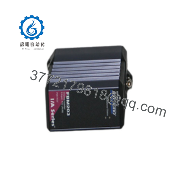
FBM203
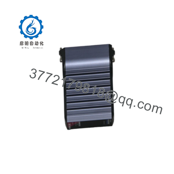
FBM203
Installation & Configuration Guide
Stage 1: Pre-Installation Preparation
- ⚠️ Safety First: Notify process operators before servicing temperature loops. Verify that active control loops assigned to the module are shifted to MANUAL mode. Obtain hot-work permits if working in hazardous classified locations (Class I, Div 2 / Zone 2).
- Tools Required: Grounded ESD wrist strap, small slotted screwdriver (2.5 mm) for baseplate lock release, wire markers, digital multimeter (Fluke 87V or equivalent), Foxboro Control Software (ICC or FoxDraw / Foxboro EVO Control Software).
- Data Backup: Export and save the current System Definition file and Block Configuration parameters (
AINblocks) associated with the target FBM letter/number designation. Note the letterbug/module address assigned to the baseplate slot.
Stage 2: Removing the Old Module
- Attach your ESD wrist strap to a verified enclosure earth ground point.
- Press the red/black module release latch located on the top and bottom edge of the FBM203 faceplate.
- Carefully pull the FBM203 straight out from its baseplate slot to avoid bending or twisting the rear edge-connector pins.
- Inspect the baseplate connector receptacle for dust, corrosion, or foreign debris. Do not touch the backplane pins with bare hands.
- Place the removed module immediately into a conductive ESD shield bag.
Stage 3: Installing the New Module
- Confirm the part number matches: P0917MC (FBM203).
- Verify that the keying pins on the rear of the new module align with the baseplate slot pattern to ensure correct physical placement.
- Align the module with the baseplate guide rails and push firmly straight back until the top and bottom retention latches snap securely into place.
- Verify that field wiring on the associated Termination Assembly (TA) matches the required RTD lead pinout (excitation +, sense +, sense −, excitation −).
Stage 4: Power-On & Testing
- Observe the top LED indicator sequence during power-up:
- RED (Solid): Module performing power-on self-test (POST).
- GREEN (Flashing): Self-test passed; waiting for communications from the Field Control Processor (FCP/ZCP).
- GREEN (Solid): Module online and communicating normally on the 2 Mbps Module Fieldbus.
- Open Foxboro System Manager / System Definition software and verify the FBM status reads
ONLINE. - Check the channel input values on active
AINblocks. Inject a known resistance value using a precision RTD calibrator to verify channel scaling and calibration. - ⚠️ Troubleshooting Note: If the module LED remains solid RED or shows a red error state, verify that the module letterbug address in software matches the physical baseplate slot position, and ensure the baseplate power supply delivers a stable 24 V DC (21.6–26.4 V DC operating range).
SOP Quality Transparency
To eliminate operational risk and ensure drop-in reliability for critical process controls, every Foxboro unit passes through a rigorous 5-step quality verification procedure prior to dispatch:
- Inbound Inspection & Traceability:
- Origin traceability verification against OEM batch documentation and serial registry.
- Visual inspection for edge-connector contact plating wear, latch stress cracks, housing discoloration, or component thermal degradation.
- Live Functional Testing:
- Installation into a genuine Foxboro I/A Series test rack with redundant Field Control Processors (FCP270 / FCP280).
- Full 8-channel analog input simulation using a multi-channel RTD decade box simulating Pt 100 profiles across −200°C to +850°C.
- Live fieldbus communication verification testing dual-redundant Bus A and Bus B line switching.
- Continuous 24-hour thermal burn-in under full load in an elevated-temperature test bay. Official QC Test Report generated and archived per unit serial number.
- Electrical Parameter Testing:
- High-potential insulation testing (500 V DC) verifying 1500 V AC galvanic isolation between field input terminals, module power ground, and fieldbus channels.
- Current draw verification on the 24 V DC baseplate bus using a calibrated Fluke 87V.
- Firmware & Configuration Verification:
- Hardware revision code and internal EEPROM firmware readouts documented.
- Module identification and diagnostic registers verified to ensure full compatibility with I/A Series software versions V8.x, EcoStruxure Foxboro DCS, and legacy CP systems.
- Final QC & Packaging:
- QC inspector sign-off and application of date-coded inspection seal.
- Sealed inside anti-static ESD shielding packaging with humidity indicator cards.
- Packed in custom-cut high-density anti-vibration foam inside a heavy-duty corrugated export box labeled with exact part numbers and serial codes.
Technical Pitfall & Survival Guide
- ❗ Mismatching 2-Wire, 3-Wire, and 4-Wire Termination Assemblies (TAs):
- Issue: Severe temperature offset errors or open-circuit alarms (
BADstatus) after swapping an module. - Avoidance: The requires a matching Foxboro Termination Assembly (e.g., P0916BC, P0916BX) wired specifically for the chosen RTD type. You cannot wire a 4-wire RTD to a 3-wire TA terminal block without setting the corresponding jumpers or software channel configuration parameters correctly.
- Field Note: I once spent three hours troubleshooting a boiler feed pump temperature reading that was off by +18°C. A technician had installed a 3-wire RTD on a terminal assembly configured for 2-wire operation without lead-wire compensation jumpers. Double-check your TA part number and jumper configuration against the Foxboro System Engineering manual.
- Issue: Severe temperature offset errors or open-circuit alarms (
- ❗ Incorrect Baseplate Slot Keying:
- Issue: Module will not seat fully into the baseplate, or connector pins suffer physical damage.
- Avoidance: Foxboro baseplates feature mechanical keying pegs to prevent inserting the wrong module type into an assigned slot. Never force a module onto a baseplate.
- Field Note: If an does not slide smoothly onto the backplane, stop immediately. Check if the red plastic keying pins on the baseplate slot match the notch pattern on the rear of the P0917MC housing. Forcing the unit can bend the gold-plated edge contacts, requiring a full baseplate replacement.
- ❗ Fieldbus Communication Timeout Due to Baseplate Termination:
- Issue: flashes green indefinitely or toggles between
ONLINEandOFFLINEstatus. - Avoidance: Ensure the baseplate chain is properly terminated with an end-of-bus terminator (P0916RB or equivalent) on the last physical baseplate position.
- Field Note: When expanding an I/A Series rack or replacing an end-position module, ensure the fieldbus terminator wasn’t accidentally knocked loose. Without proper 100 Ω bus termination, high-speed 2 Mbps HDLC signals experience edge reflections that knock modules offline unpredictably.
- Issue: flashes green indefinitely or toggles between
- ❗ Ungrounded Shield Connections Causing Signal Noise:
- Issue: Temperature readings jump erratically or show high-frequency noise spikes on the DCS trend display.
- Avoidance: Connect signal cable shields at one point only—typically at the ground bus bar near the fieldbus baseplate rack—and isolate the shield wire at the field instrument junction box.
- Field Note: Grounding RTD cable shields at both the field sensor head and the control cabinet creates a ground loop. Heavy electrical currents from nearby motor variable frequency drives (VFDs) will couple onto the sensitive RTD millivolt signals, ruining your calibration.
Frequently Asked Questions (FAQ)
Can the Foxboro be hot-swapped while the system is running?
Yes. The is designed for live insertion and removal (hot-swapping) on energized Foxboro DIN-rail baseplates. The backplane connectors feature staggered pin lengths so that power and ground make contact before signal lines, preventing voltage transients during hot-swap operations.
What is the difference between the Foxboro and the FBM203c?
The standard (P0917MC) features standard circuit board construction suitable for typical control room environments (Class G1/G2). The FBM203c variant includes conformal coating on the internal printed circuit board assemblies, providing enhanced protection against corrosive atmospheric environments containing sulfur, chlorine, or high ambient humidity (Class G3 ISA environment rating).
Does the support thermocouple inputs?
No. The is specifically optimized for resistance temperature detectors (RTDs) and direct ohm measurements. For thermocouple inputs, you must use the Foxboro FBM202 (P0926EQ) 8-channel millivolt/thermocouple input module.
Do I need to recalibrate the when replacing an existing unit?
No field calibration is required upon installation. The is factory-calibrated across its operating range and features automated internal drift compensation. Once inserted into the baseplate slot, the Field Control Processor automatically downloads the saved channel configuration parameters (RTD curve, filtering time, unit ranges) to the new module.
How does your new surplus inventory compare to factory-direct units?
Our new surplus modules are unused OEM original units sourced from project spares, cancelled plant builds, or system integrator inventory. Each module undergoes full live testing on a Foxboro I/A Series test bed to verify fieldbus communication and channel accuracy, allowing you to bypass long OEM factory lead times while maintaining system integrity.



