
 WhatsApp: +86 16626708626
 Email:
  Phone: +86 16626708626
Description
Key Technical Specifications
| Parameter | Value |
|---|---|
| Product Model | FBM207B |
| Ordering Number | P0914WH |
| Manufacturer | Foxboro (Invensys / Schneider Electric) |
| System Platform | Foxboro I/A Series DCS |
| Product Type | Discrete Contact Input Interface Module |
| Input Channels | 16 isolated independent channels |
| Input Type | 24 V DC contact sense |
| Contact Wetting Voltage | Supplied by module |
| Input Current | Approximately 2 mA per channel |
| Channel Isolation | Individual channel isolation |
| Communication Interface | I/A Series 2 Mbps Fieldbus |
| Fieldbus Configuration | Single or redundant installation |
| Termination Assembly | Type C compression terminal / Type 4 cable |
| Compatible TA | P0916JS, P0916PP, P0916XT depending on configuration |
| Response Time | Configurable input filtering |
| Input Protection | Current-limited contact excitation |
| Power Supply | 24 V DC system supply |
| Power Consumption | Approximately 8 W maximum |
| Operating Temperature | −40 to +70 °C (depending on installation configuration) |
| Storage Temperature | −55 to +85 °C |
| Humidity | 5 to 95 % RH, non-condensing |
| Mounting | I/A Series FBM modular baseplate |
| Module Dimensions | Approximately 102 × 45 × 104 mm |
| Weight | Approximately 284 g |
The Foxboro FBM207B P0914WH is a 16-channel isolated contact input module for Foxboro I/A Series DCS systems. It is designed for 24 V DC contact sensing applications such as switch monitoring, equipment status feedback, alarms, and discrete process signals.
Product Introduction
The Foxboro FBM207B P0914WH is an I/A Series discrete input Fieldbus Module used to acquire 24 V DC contact signals from field devices and transmit status information to the Foxboro DCS through the Fieldbus network. Typical applications include motor running feedback, valve position switches, alarm contacts, and interlock monitoring.
The module provides 16 isolated input channels, channel-level protection, and compatibility with redundant I/A Series Fieldbus architectures. It is commonly maintained in legacy process plants where replacing individual I/O modules is preferred over a complete DCS migration.
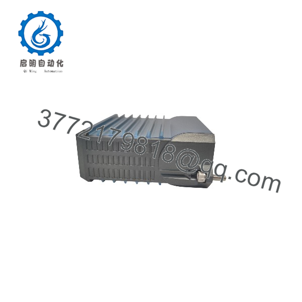
FBM207B P0914WH
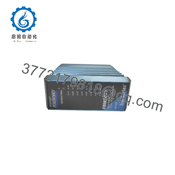
FBM207B P0914WH
Installation & Configuration Guide
Stage 1: Pre-Installation Preparation (Approx. 10 minutes)
⚠️ Safety First
- Notify the control room before removing the FBM207B.
- Confirm affected alarms, permissives, and interlocks are managed safely.
- Apply lockout/tagout procedures when cabinet access requires power isolation.
- Remove module power and wait at least 5 minutes before handling wiring.
Tools Required
- ESD wrist strap
- PH1 screwdriver
- Digital multimeter
- Wire labels
- Smartphone for configuration photos
Data Backup
Before removal:
- Record the FBM207B model and P0914WH ordering code.
- Photograph the module location and termination wiring.
- Document each input channel assignment.
- Record Fieldbus address and module slot position.
- Save the current I/O configuration from the I/A Series workstation.
Stage 2: Removing the Old Module (Approx. 10 minutes)
Steps
- Open the I/A Series cabinet.
- Confirm the correct FBM207B slot.
- Label all field wiring before disconnecting.
- Disconnect the termination wiring carefully.
- Release the module locking mechanism.
- Pull the module straight outward from the baseplate.
- Inspect the connector pins and mounting area.
⚠️ Note:
Keep the original module until the replacement passes communication and channel testing. Legacy Foxboro systems often depend on exact module position, termination type, and database configuration.
Stage 3: Installing the New Module (Approx. 10 minutes)
Steps
- Wear an ESD strap before handling the replacement unit.
- Verify:
- Model:
- Ordering code: P0914WH
- Correct termination assembly
- Correct Fieldbus configuration
- Configuration Clone (Critical):
- Match module slot position.
- Verify all 16 input channel assignments.
- Confirm contact sensing voltage.
- Copy input filtering settings.
- Confirm alarm and sequence logic mapping.
- Insert the module into the FBM baseplate.
- Secure the locking mechanism.
- Reconnect field wiring.
Self-Checklist
- P0914WH confirmed
- Termination assembly verified
- Field wiring labeled correctly
- Module seated correctly
- I/O database matches hardware
Stage 4: Power-On & Testing (Approx. 15 minutes)
Pre-Power Check
- Verify 24 V DC supply availability.
- Check contact wiring polarity.
- Confirm no shorts exist between input terminals.
Power-On Steps
- Restore cabinet power.
- Observe FBM status LEDs.
- Verify Fieldbus communication.
- Check module health status in the Foxboro workstation.
- Simulate contact inputs.
- Verify all 16 input points update correctly.
⚠️ Troubleshooting Note
- If the module does not communicate, check Fieldbus termination and module addressing.
- If inputs remain inactive, verify contact wetting voltage and field wiring.
- If signals chatter, review input filter timing.
Frequently Asked Questions (FAQ)
Q1: Can the Foxboro be hot-swapped?
Some Foxboro I/A Series installations support online replacement, but this depends on the installed baseplate, adapter hardware, and system revision. Confirm the plant maintenance procedure before removing an active module.
Do not assume every I/A Series cabinet supports live replacement.
Q2: Is the obsolete?
Yes, the belongs to the mature Foxboro I/A Series product family. Many facilities continue operating I/A Series systems, so replacement demand remains. Availability depends mainly on remaining inventory and tested surplus stock.
Q3: What is the difference between FBM207, , and FBM207C?
These modules have different discrete input applications:
- FBM207: Voltage monitoring input module.
- 24 V DC contact sense input module.
- FBM207C: 48 V DC contact sense input module.
They are not direct substitutes. Always verify the field signal type before ordering.
Q4: Will replacing the erase my DCS configuration?
No. The control strategy and I/O database remain stored in the Foxboro control system. However, the replacement module must match:
- Module type.
- Slot location.
- Termination assembly.
- Channel assignments.
A hardware swap without configuration verification can create incorrect status indications.
Q5: Why is the cheaper than a new OEM module?
Legacy DCS modules often come from:
- Plant spare inventory.
- Project excess stock.
- System upgrade programs.
- Equipment retirement stock.
Price differences usually reflect availability and lifecycle status.
The condition should always be stated clearly:
- New Original / New Surplus: Unused inventory.
- Factory Sealed: Original unopened packaging where available.
- Refurbished (tested): Function-tested after inspection.
Q6: What inspection process should be completed before installing a surplus ?
A proper inspection process should include:
Inbound Inspection & Traceability
- Verify supplier records.
- Confirm model and label.
- Check serial number markings.
- Inspect housing condition.
- Confirm no corrosion, scratches, repair marks, or contamination.
- Audit accessories.
Live Functional Testing
Test environment:
- Genuine Foxboro I/A Series FBM test rack.
Testing steps:
- Power-up LED verification.
- Fieldbus communication test.
- 24 V DC contact simulation.
- All 16 input channel verification.
- Continuous operation monitoring.
- Test report generation.
Electrical Parameter Testing
- Insulation resistance test using 500 V Megger where applicable.
- Ground continuity check.
- Input channel electrical verification.
Firmware & Configuration Verification
- Record hardware revision.
- Document module identification.
- Photograph labels and connectors.
- Save test records.
Final QC & Packaging
- QC inspector approval.
- Anti-static ESD bagging.
- Bubble wrap protection.
- Heavy-duty corrugated boxing.
- QC Passed label with inspection date.
Q7: What are the most common replacement mistakes?
❗ The most common mistake is installing the correct module with the wrong termination or field voltage assumption.
I have seen maintenance teams replace an successfully at the hardware level but lose commissioning time because the channel mapping did not match the original DCS database.
Common problems:
- Ordering FBM207 instead of .
- Incorrect termination assembly.
- Missing channel documentation.
- Wrong Fieldbus address.
- Damaged connector pins during installation.
Take photos before removal. Record the slot and every channel assignment. Those simple checks prevent most legacy Foxboro replacement delays.



