
 WhatsApp: +86 16626708626
 Email:
  Phone: +86 16626708626
Description
Key Technical Specifications
| Parameter | Value |
|---|---|
| Model | FBM211 |
| Manufacturer | Foxboro (Schneider Electric) |
| Product Type | Analog Input Fieldbus Module |
| Series | Foxboro I/A Series DCS |
| Input Channels | 16 Analog Inputs |
| Supported Signals | 4–20 mA, configurable analog inputs |
| Isolation | Channel-to-system isolation |
| Communication | Foxboro Fieldbus Interface |
| Mounting | DIN rail / Fieldbus baseplate |
| Operating Temperature | Industrial operating range (refer to OEM datasheet) |
| Diagnostics | Continuous module self-diagnostics |
| Application | Process measurement and monitoring |
Product Introduction
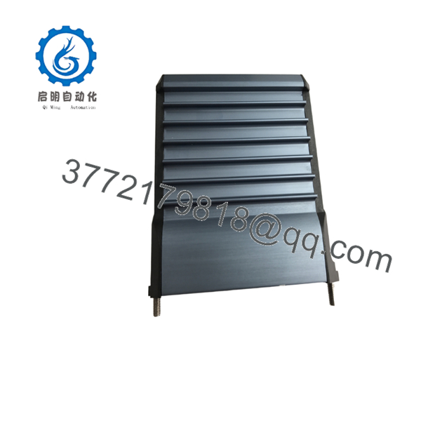
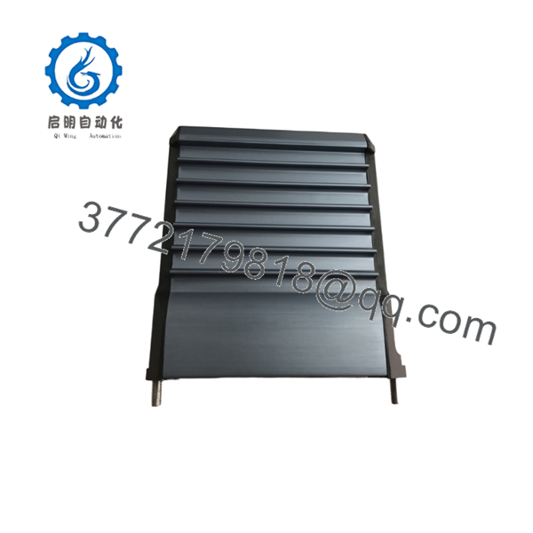
The Foxboro FBM211 is a 16-channel analog input module designed for the Foxboro I/A Series distributed control system (DCS). It converts field analog process signals into digital data for control strategies involving pressure, temperature, flow, level, and other continuous process variables.
Engineers commonly select the FBM211 for applications requiring stable analog signal acquisition, built-in diagnostics, and compatibility with existing Foxboro installations. Before installation, verify hardware revision, firmware compatibility, and field termination requirements against the existing system configuration.

- FBM211
- FBM211
Installation & Configuration Guide
Stage 1 – Pre-Installation Preparation (10 Minutes)
⚠️ Safety First
- Notify plant operations of the planned shutdown.
- Perform Lock-Out/Tag-Out (LOTO).
- Remove power from the cabinet.
- Wait at least 5 minutes for internal capacitors to discharge.
Tools Required
- ESD wrist strap
- PH1 screwdriver
- Digital multimeter
- Wire labels
- Smartphone for documentation
Data Backup
- Export controller configuration.
- Record module location.
- Photograph terminal wiring.
- Record any configured channel parameters.
Stage 2 – Removing the Existing Module (5 Minutes)
- Label every field cable.
- Disconnect terminal blocks carefully.
- Release the retaining latch.
- Pull the FBM straight from its mounting base.
⚠️ Keep the old module until commissioning is complete.
Inspect:
- Bent connector pins
- Dust contamination
- Moisture
- Corrosion
Stage 3 – Installing the New FBM211 (10 Minutes)
- Wear an ESD strap.
- Confirm the replacement is .
- Compare hardware revision with the removed unit.
- Install the module until it locks securely.
- Reconnect all terminal wiring.
- Verify every channel matches the original wiring documentation.
Checklist:
- ✔ Module fully seated
- ✔ Wiring secure
- ✔ Terminal numbers verified
- ✔ Ground connection confirmed
Stage 4 – Power-Up & Commissioning (10 Minutes)
- Measure the 24 V supply before energizing.
- Apply power to the cabinet.
- Observe module LEDs.
- Connect using Foxboro engineering software.
- Confirm communication status.
- Verify all analog input values.
- Simulate several process signals before returning the system to service.
⚠️ Troubleshooting
No communication
- Verify baseplate installation.
- Check Fieldbus communication.
- Confirm module compatibility.
Incorrect analog values
- Verify transmitter calibration.
- Check wiring polarity.
- Confirm channel configuration.
Module fault LED
- Review diagnostic messages.
- Verify hardware revision compatibility.
- Replace the module if internal diagnostics indicate hardware failure.
Frequently Asked Questions (FAQ)
Q1. Can the be hot-swapped?
Generally, no. Although some Foxboro architectures support online maintenance, always follow the plant’s maintenance procedure and Schneider Electric documentation before replacing an I/O module under power. An improper replacement can interrupt communication or affect adjacent modules.
Q2. Is the obsolete?
Many modules remain in service worldwide. Depending on the manufacturing revision, availability may be limited, making new surplus and professionally tested units common sourcing options for maintenance inventories.
Q3. Does replacing the erase my control strategy?
No. The control strategy resides in the controller rather than the analog input module. However, channel configuration, addressing, and engineering database settings should be verified before returning the system to operation.
Q4. What should I check before ordering a replacement?
Compare:
- Hardware revision
- Firmware compatibility
- Baseplate compatibility
- Terminal assembly
- System software version
- Existing I/O configuration
Taking photos before removal helps avoid installation errors.
Q5. Why are New Surplus modules typically less expensive than buying directly from the OEM?
New Surplus inventory usually comes from unused project stock, canceled projects, or excess inventory rather than current production. These modules are unused but may have older manufacturing dates. Confirm the condition, traceability, and test documentation before purchasing.
Q6. What analog signals does the support?
The is primarily intended for industrial analog process measurements such as 4–20 mA transmitters used for pressure, temperature, flow, and level instrumentation. Always verify the exact supported input types and ranges in the OEM documentation for your hardware revision.



