
 WhatsApp: +86 16626708626
 Email:
  Phone: +86 16626708626
Description
3. Key Technical Specifications
| Parameter | Value |
|---|---|
| Input Channels | 32 group-isolated |
| Input Type | Voltage monitor or contact sense (TA dependent) |
| On-State Voltage (basic DC) | 15 to 30 V DC |
| Off-State Voltage | 0 to 5 V DC |
| Input Current | 2.2 mA typical at 30 V DC |
| Source Resistance Limits | On-state ≤ 1 kΩ at 15 V DC; Off-state ≥ 100 kΩ at 30 V DC |
| Supported Field Voltages | 15–60 V DC, 120 V AC / 125 V DC, 240 V AC (via appropriate TA) |
| Filter / Debounce Time | Configurable: none, 4, 8, 16, or 32 ms |
| Maximum Pulse Count Rate | 250 Hz |
| Isolation | Group isolation from earth/ground (TA dependent) |
| Power Supply | 24 V DC +5 % / –10 % (redundant capable) |
| Power Consumption | 3 W maximum |
| Heat Dissipation | 5 W maximum |
| Operating Temperature | –20 to +70 °C (module) |
| Relative Humidity | 5 to 95 % non-condensing |
| Dimensions (module) | 102 mm H × 45 mm W × 104 mm D (approx.) |
| Weight | Approx. 280–320 g |
| Mounting | Modular baseplate; supports single or redundant pair with adapter |
4. Product Introduction
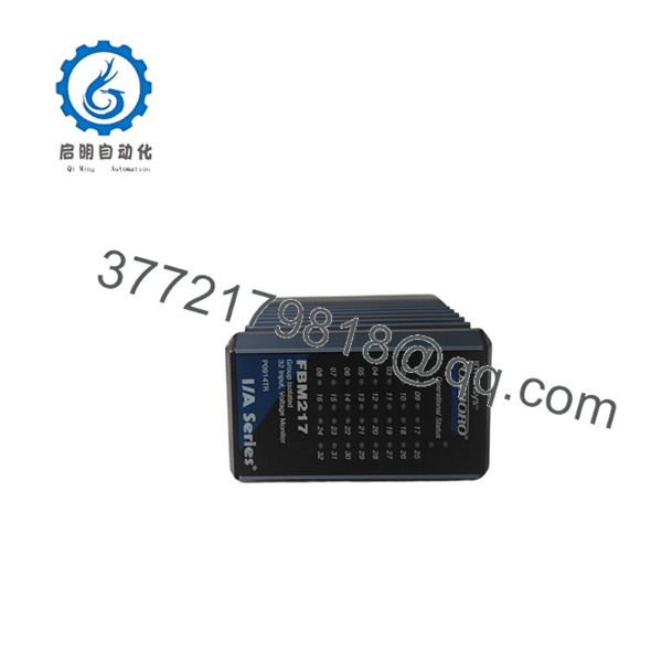
The Foxboro FBM217 P0914TR is a 32-channel discrete input Fieldbus Module for the I/A Series and Foxboro Evo DCS. Each channel accepts a 2-wire discrete signal from DC voltage sources or contact closures. The exact voltage range and isolation characteristics are determined by the associated termination assembly.
The module executes Discrete Input, Ladder Logic, Pulse Count, and Sequence of Events functions with configurable input filtering. It can operate as a single module or as a redundant pair using a redundancy adapter and common TA. This high-density discrete input solution is selected for monitoring switch status, relay contacts, and voltage presence in process and discrete control applications.

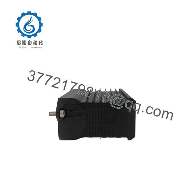
- FBM217 P0914TR
- FBM217 P0914TR
5. Troubleshooting Quick Reference
| Symptom | Possible Cause | Relevance to this Part | Quick Check Method | Recommendation |
|---|---|---|---|---|
| All channels read Off / no status change | Missing TA cable, open field wiring, or no field voltage | ✅ High | Verify Type-4 (or correct) cable seating; measure voltage at TA terminals | Confirm field power and wiring before replacing module |
| Individual channel stuck Off or On | Open/shorted field contact or wiring to that channel | ✅ High | Measure voltage or continuity at the specific TA channel terminals | Swap field wires to a known-good channel to isolate the fault |
| Intermittent or noisy channel status | Loose terminal, vibration, or incorrect filter setting | ✅ Medium | Check terminal torque and cable shield; review filter time configuration | Re-terminate with proper ferrules; adjust debounce filter if needed |
| Module status LED indicates fault | Baseplate power or Fieldbus communication problem | ❌ Low | Measure 24 V DC at baseplate; check adjacent modules and Fieldbus paths | Resolve power or communication issue first |
| Pulse count inaccurate | Filter time too long or field pulse rate exceeds 250 Hz | ✅ Medium | Verify pulse frequency with oscilloscope or counter; check filter setting | Reduce filter time or confirm field device rate is within specification |
| Redundant pair quality mismatch | Adapter or cable problem between modules | ✅ High | Inspect redundancy adapter seating and shared TA cable | Reseat adapter and cables; confirm both modules see identical field signals |
If these checks do not resolve the issue, capture photos of the module front, TA terminals, cable ends, and a system diagnostic log, then contact technical support.
6. Frequently Asked Questions (FAQ)
Q: What voltages does the FBM217 support? A: The module itself is a discrete input interface. Actual field voltage ranges (15–60 V DC, 120 V AC/125 V DC, or 240 V AC) are determined by the selected termination assembly. Always match the TA to the field signal level.
Q: Can the FBM217 be used in a redundant configuration? A: Yes. It is redundant-ready. Install two FBM217 modules with a redundancy adapter and a common termination assembly for Master/Tracker operation.
Q: Does it support pulse counting and Sequence of Events? A: Yes. The module supports Discrete Input, Ladder Logic, Pulse Count (up to 250 Hz), and Sequence of Events functions with configurable input filter times.
Q: What is the difference between group isolation and channel isolation on this module? A: The provides group isolation. Specific TAs determine whether the 32 channels are group-isolated or offer additional conditioning. Refer to the PSS and TA documentation for the exact isolation provided by your combination.
Q: Is calibration required? A: No. The module and associated termination assemblies do not require field calibration.
Q: Why are surplus units priced lower than factory-new listings? A: Most available stock is New Surplus—never installed, from excess project inventory. Units are inspected for physical condition. A 1-year warranty is provided; the original OEM warranty does not transfer with surplus material.
Q: Which baseplate and cable are required? A: Install on a standard RX3i / I/A Series modular baseplate. Use the termination cable type specified for the chosen TA (commonly Type 4). Confirm exact part numbers against the current Product Specification Sheet.



