
 WhatsApp: +86 16626708626
 Email:
  Phone: +86 16626708626
Description
Key Technical Specifications
| Parameter | Value |
|---|---|
| Model | FBM227 |
| Manufacturer | Foxboro (Schneider Electric) |
| Product Type | Hybrid Analog/Digital I/O Module |
| Analog Inputs | 4 individually isolated channels (0–10 VDC) |
| Analog Outputs | 2 individually isolated channels (0–10 VDC) |
| Digital Inputs | 4 channels (isolated in two channel pairs) |
| Digital Outputs | 4 channels (isolated in two channel pairs) |
| Analog Isolation | Individual channel isolation |
| Digital Isolation | Pair isolation |
| Supported Functions | DPIDA and MDACT local control support |
| Configurable Features | Input resolution, fail-safe mode, input filter, pulse output interval |
| Communication | Foxboro Module Fieldbus |
| Mounting | Standard or Compact 200 Series baseplate |
The FBM227 combines analog and digital I/O on a single module, providing four 0–10 VDC analog inputs, two 0–10 VDC analog outputs, four digital inputs, and four digital outputs. It can execute either Analog I/O or Digital I/O application programs and supports local DPIDA or MDACT control functions.
Product Introduction
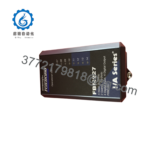
The Foxboro FBM227 is a mixed analog and discrete I/O interface module designed for the Foxboro Evo™ and legacy I/A Series distributed control systems. By integrating voltage analog I/O and digital I/O within a single fieldbus module, it reduces cabinet space while simplifying wiring for applications requiring both continuous and discrete process control.
A distinguishing feature of the FBM227 is its support for DPIDA (Advanced PID) and MDACT (Motor Drive Actuator Control) algorithms executed locally within the module. This allows faster response for selected control loops and actuator applications while reducing controller loading.
Installation & Configuration Guide
Stage 1 – Pre-Installation Preparation (10 Minutes)
⚠️ Safety First
- Notify plant operations before shutdown.
- Perform Lock-Out/Tag-Out (LOTO).
- Remove cabinet power.
- Wait at least 5 minutes for internal energy to dissipate.
Required Tools
- ESD wrist strap
- Phillips screwdriver
- Digital multimeter
- Wire identification labels
- Smartphone for recording wiring
Before Removal
- Back up the Foxboro configuration database.
- Record all analog scaling parameters.
- Document digital I/O assignments.
- Photograph terminal wiring before disconnecting cables.
Stage 2 – Remove the Existing Module (5 Minutes)
- Label every field cable.
- Disconnect the termination assembly.
- Release the retaining latch.
- Remove the module without twisting.
⚠️ Keep the original module available until all analog and digital channels have been verified.
Inspect:
- Backplane connectors
- Ground terminals
- Dust contamination
- Corrosion
- Bent connector pins
Stage 3 – Install the New FBM227 (10 Minutes)
- Wear an ESD wrist strap.
- Verify the replacement model number.
- Install the module completely into the baseplate.
- Reconnect the termination assembly.
- Verify analog and digital wiring individually.
Installation Checklist
- ✔ Correct module installed
- ✔ Analog wiring verified
- ✔ Digital wiring verified
- ✔ Ground connection confirmed
- ✔ Module securely latched
Stage 4 – Power-On & Functional Test (10 Minutes)
- Verify the 24 VDC system supply.
- Restore cabinet power.
- Observe module status LEDs.
- Connect using Foxboro engineering software.
- Verify analog input and output calibration.
- Test every digital input and output.
- Confirm DPIDA or MDACT operation if configured.
⚠️ Common Startup Issues
Incorrect analog voltage
- Verify field scaling.
- Check sensor wiring.
- Confirm output configuration.
Digital output inactive
- Verify external load wiring.
- Check output configuration.
- Measure output voltage.
Module communication fault
- Verify Fieldbus communication.
- Inspect the baseplate connector.
- Confirm firmware compatibility.

- FBM227
Frequently Asked Questions (FAQ)
Q1. What makes the different from standard analog I/O modules?
Unlike conventional analog modules, the combines analog inputs, analog outputs, digital inputs, and digital outputs in a single module. It also supports local DPIDA and MDACT execution for faster process response.
Q2. How many I/O channels are available?
The provides:
- 4 × 0–10 VDC analog inputs
- 2 × 0–10 VDC analog outputs
- 4 digital inputs
- 4 digital outputs
This mixed-I/O design reduces the number of modules required in small or specialized control applications.
Q3. What is DPIDA support?
DPIDA (Distributed PID Algorithm) allows selected PID control loops to execute directly within the instead of entirely in the controller, reducing communication overhead and improving response time for certain applications.
Q4. What is MDACT used for?
MDACT is intended for motorized actuator control, supporting three-state (Raise/Off/Lower) output logic commonly used with valve actuators and positioning devices.
Q5. Can the replace the older FBM17?
Yes. Schneider Electric identifies the as providing the functionality formerly supplied by the 100 Series FBM17, making it a common migration option when upgrading to the 200 Series platform.
Q6. Where is the typically installed?
The is commonly used in refinery, chemical, power generation, water treatment, and other continuous-process industries where a combination of analog measurement and discrete control is required within a compact I/O footprint.



