
 WhatsApp: +86 16626708626
 Email:
  Phone: +86 16626708626
Description
Key Technical Specifications
| Parameter | Value |
|---|---|
| Manufacturer | Foxboro (Schneider Electric / Invensys) |
| Model Number | FBM237 |
| Part Number | P0914XS |
| System Platform | Foxboro I/A Series |
| Module Type | Channel Isolated Analog Output Interface Module |
| Output Channels | 8 channels |
| Output Signal Range | 0 to 20 mA DC |
| Output Isolation | Galvanically isolated channels and ground isolation |
| Redundancy Support | Redundant-ready (dual FBM237 configuration) |
| Field Device Compatibility | Compatible with HART® field devices |
| Termination Interface | Foxboro I/A Series termination assemblies |
| Installation Environment | Class G3 harsh environment compatible |
| Weight | Approx. 0.3–0.7 kg depending on packaging configuration |
| Application | Process control analog output loops |
Product Introduction
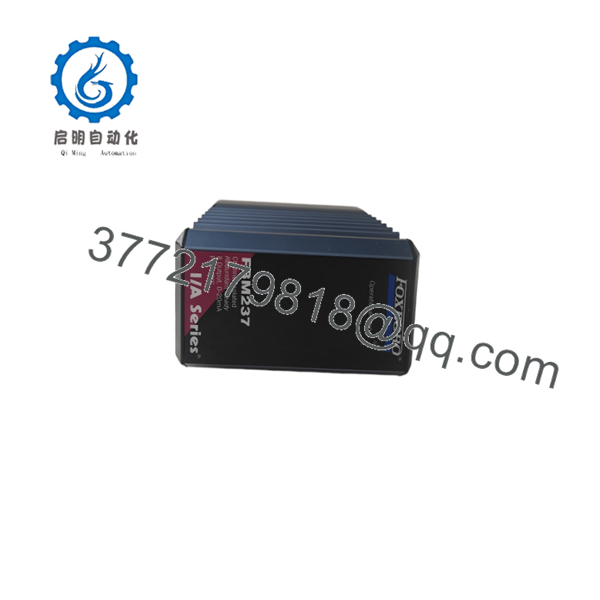
The Foxboro FBM237 P0914XS is an I/A Series distributed control system analog output interface module designed for eight isolated 0-20 mA output channels. It provides the signal interface between the Foxboro control processor and field devices such as control valves, actuators, and current-driven instruments.
The module supports single or redundant operation, allowing plants to maintain output availability during a module fault condition or replacement activity. It is commonly used in process industries where existing Foxboro I/A Series installations require direct replacement of aging I/O hardware.

- FBM237 P0914XS
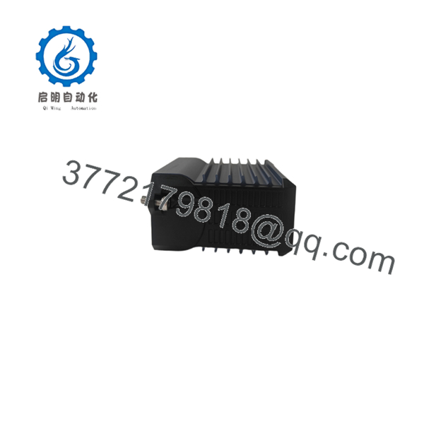
- FBM237 P0914XS
Installation & Configuration Guide
Stage 1: Pre-Installation Preparation (Estimated Time: 10 minutes)
⚠️ Safety First
- Notify operations before removing the module.
- Place the process loop into a safe operating condition.
- Apply lockout/tagout procedures before accessing the I/O cabinet.
- Confirm cabinet power status before module removal.
Tools Required
- ESD wrist strap
- PH1 screwdriver
- Digital multimeter
- Wire labels
- Smartphone or camera for configuration records
Data Backup
Before replacement:
- Record the current FBM237 slot location.
- Photograph termination assembly wiring.
- Document channel assignments.
- Verify Foxboro I/A Series configuration database settings.
- Record module redundancy arrangement if installed.
Stage 2: Removing the Old Module (Estimated Time: 10 minutes)
- Remove the protective cover or module retaining mechanism.
- Label all field wiring connections before disconnecting.
- Release the module locking tabs.
- Pull the straight outward from the carrier.
- Inspect the backplane connector for:
- Bent pins
- Dust contamination
- Physical damage
⚠️ Keep the removed module until commissioning is complete.
The old unit is often the fastest reference for jumper settings, labels, and wiring verification.
Stage 3: Installing the New Module (Estimated Time: 10 minutes)
- Wear an ESD wrist strap before handling the replacement .
- Confirm the replacement part number matches:
- Verify the termination assembly compatibility.
- Insert the module into the correct I/O carrier position.
- Confirm the module seats completely.
- Reconnect field wiring using the original channel mapping.
Configuration Checklist
☐ Correct module position
☐ Correct termination assembly
☐ Wiring labels match
☐ Redundancy configuration verified
☐ Module fully seated
Stage 4: Power-On & Testing
- Restore cabinet power.
- Observe module status indicators.
- Verify the Foxboro control system recognizes the .
- Confirm channel configuration in the I/A Series database.
- Perform output loop checks:
- 0 mA output verification
- Mid-scale output verification
- Full-scale output verification
⚠️ Troubleshooting Note
If outputs remain inactive:
- Check I/O database configuration.
- Verify termination assembly wiring.
- Confirm module addressing.
- Check whether the replacement module revision matches the existing system configuration.
Firmware and hardware revision differences should be verified against the OEM documentation before installation.
Frequently Asked Questions (FAQ)
Q1: Can the Foxboro P0914XS be hot-swapped?
It depends on the installed Foxboro I/A Series hardware configuration. The supports redundant operation, but you should verify the carrier, power arrangement, and site procedures before removing a module under power. For standard replacement work, isolate power first.
Q2: Is the P0914XS obsolete?
Yes. The belongs to the Foxboro I/A Series product family, and many distributors classify as discontinued or obsolete. Existing plants continue using these modules because replacing the complete control platform can require significant engineering effort and downtime.
Q3: What is the direct replacement for ?
There is no universal drop-in replacement without checking the exact Foxboro system revision, carrier hardware, and control database configuration. Migration options may include newer Foxboro control platforms or modernization solutions, but compatibility must be verified before ordering.
Q4: Will I lose configuration data when replacing an ?
The module itself does not normally contain the complete control strategy. The Foxboro I/A Series configuration database maintains the engineering configuration. However, always verify channel assignments and module definitions before replacement.
Q5: Why is this module available below OEM pricing?
Most modules on the market come from industrial surplus inventories, unused spare stock, or tested refurbished channels. Buyers should confirm condition before purchase:
- New Original / New Surplus
- Factory packaging status
- Test report availability
- Warranty terms
Q6: What should I check before ordering ?
Confirm:
- Existing module number:
- Part number:
- Foxboro I/A Series compatibility
- Required output type: 0-20 mA
- Redundant or single-module installation
- Existing termination assembly model
A wrong I/O module selection can create commissioning delays even when the physical module appears identical.
Q7: Does support HART field devices?
Yes. The output channels are electrically compatible with HART field devices when used within the supported Foxboro system configuration.
Product Availability Note:
is typically sourced through industrial automation spare-part channels because it belongs to an established Foxboro I/A Series installed base. Confirm exact condition, test records, and warranty coverage before purchase.



