
 WhatsApp: +86 16626708626
 Email:
  Phone: +86 16626708626
Description
Key Technical Specifications
| Parameter | Value |
|---|---|
| Manufacturer | Foxboro (Invensys / Schneider Electric) |
| Model Number | FCP270 |
| Part Number | P0917YZ |
| Product Type | Field Control Processor 270 |
| System Platform | Foxboro I/A Series DCS |
| Processor Type | 32-bit industrial RISC processor |
| SDRAM Memory | 16 MB |
| Flash Memory | 32 MB |
| Power Supply | 24 V DC nominal, redundant input supported |
| Power Consumption | Approx. 8.5 W maximum per non-fault-tolerant module |
| Communication Interface | Foxboro I/A Series Fieldbus / Control Network communication |
| Redundancy Support | Fault-tolerant configuration using dual processor arrangement |
| Supported I/O | Foxboro FBM I/O modules through fieldbus network |
| Operating Temperature | 0 to +60 °C |
| Dimensions | Approx. 14.7 cm × 5.15 cm × 11.4 cm |
| Weight | Approx. 0.6 kg |
| Mounting | Foxboro 200 Series baseplate installation |
Product Introduction
The Foxboro FCP270 P0917YZ is a Field Control Processor used in Foxboro I/A Series distributed control systems. It executes configured control strategies, alarm processing, and regulatory control functions while communicating with FBM field I/O modules through the I/A Series architecture.
The FCP270 supports optional fault-tolerant operation using redundant processor configurations. It is widely maintained in existing process plants where I/A Series infrastructure remains operational and requires replacement processor inventory.
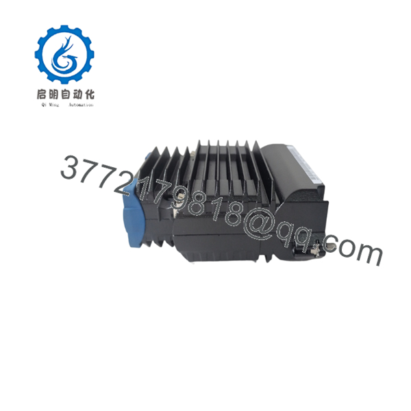
- FCP270 P0917YZ
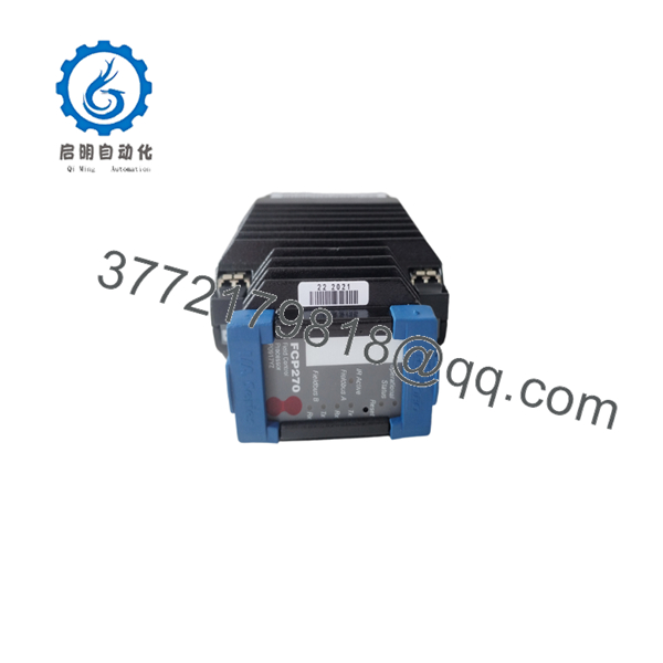
- FCP270 P0917YZ
Installation & Configuration Guide
Stage 1: Pre-Installation Preparation (Estimated Time: 15 minutes)
⚠️ Safety First
Before replacing an :
- Notify operations and obtain approval for controller intervention.
- Confirm the controlled process can tolerate controller maintenance.
- Place affected loops into a safe operating condition.
- Apply lockout/tagout procedures if cabinet power removal is required.
- Wait for DC supply discharge before handling hardware.
Tools Required
- ESD wrist strap
- Digital multimeter
- PH1 screwdriver
- Wire labels
- Smartphone/camera for documentation
Data Backup
Before removal:
- Record the current slot location.
- Photograph module labels and LED status.
- Record network addresses and controller configuration.
- Verify redundancy arrangement.
- Confirm current firmware revision if accessible.
⚠️ Do not remove the running controller before confirming the backup controller status in redundant systems.
Stage 2: Removing the Existing (Estimated Time: 10 minutes)
- Open the Foxboro I/A Series cabinet.
- Identify the processor location.
- Record all module indicators.
- Disconnect communication and power connections if required.
- Release the module retaining mechanism.
- Pull the processor straight out from the baseplate.
Inspect:
- Backplane connector pins
- Module seating area
- Dust contamination
- Physical damage
⚠️ Keep the removed processor until the replacement has completed commissioning.
Stage 3: Installing the Replacement (Estimated Time: 15 minutes)
- Verify replacement identification:
Foxboro → P0917YZ
- Check:
- Processor model
- Firmware compatibility
- Physical connector condition
- Label information
- Insert the processor into the correct baseplate position.
- Ensure the module is fully seated.
- Restore power and communication connections.
Configuration Checklist
☐ Correct processor model installed
☐ Baseplate slot verified
☐ Network connection restored
☐ Redundancy configuration checked
☐ Power voltage confirmed
Stage 4: Power-On & Testing (Estimated Time: 20 minutes)
- Apply 24 V DC power.
- Observe processor diagnostic LEDs.
- Verify communication status.
- Connect engineering workstation if required.
- Confirm:
- Controller online status
- Control database synchronization
- FBM communication
- Alarm status
- Process loop operation
⚠️ Troubleshooting Note
If the controller does not communicate:
- Check network addressing.
- Verify firmware compatibility.
- Confirm the processor is installed in the correct baseplate slot.
- Check redundant controller status.
A processor replacement without recording the original configuration can extend commissioning time significantly.
Frequently Asked Questions (FAQ)
Q1: What is the Foxboro used for?
The is the controller processor for Foxboro I/A Series DCS systems. It executes process control logic and communicates with distributed fieldbus modules.
Q2: Is a PLC CPU?
Not exactly. It performs controller functions similar to a PLC CPU, but it belongs to the Foxboro I/A Series DCS architecture and is designed for distributed process control applications.
Q3: Does support redundancy?
Yes. The supports fault-tolerant configurations using paired processor modules and compatible baseplate hardware. Verify the installed system design before replacement.
Q4: Is obsolete?
The is part of the legacy Foxboro I/A Series platform. Many plants continue operating these systems, so replacement units are normally sourced from industrial automation spare inventories.
Q5: Will replacing erase the control program?
Normally, the complete control strategy is maintained in the Foxboro system configuration environment rather than only inside the processor module. However, verify controller synchronization and database status after replacement.
Q6: Can I directly replace any with ?
Only if the existing hardware configuration matches. Check:
- Existing FCP model
- Part number
- Firmware revision
- Baseplate type
- Redundancy arrangement
A physically compatible processor may still fail to communicate if firmware or configuration versions do not match.
Q7: What should I request before purchasing an ?
For legacy controller modules, request:
- Serial number photos
- Condition confirmation
- Functional test report
- Firmware information
- Warranty terms
For critical process systems, verify the replacement unit before planned shutdown installation.



