
 WhatsApp: +86 16626708626
 Email:
  Phone: +86 16626708626
Description
Key Technical Specifications
| Parameter | Value |
|---|---|
| Manufacturer | Foxboro / Invensys |
| Product Family | I/A Series |
| Module | IPM02 |
| Part Number | P0904HA |
| Product Type | DCS Power Supply |
| System | Foxboro I/A Series |
| Primary Function | I/A Series system power conversion/distribution |
| Associated Components | CP-series processors, FBM-series I/O and associated I/A Series hardware |
| System Architecture | Foxboro I/A Series DCS |
| Installation | I/A Series system power subsystem |
| Replacement Status | Legacy / field-maintained component |
| Verification Requirement | Confirm nameplate, revision, rack configuration, and electrical specifications before installation |
Foxboro references consistently associate IPM02 with P0904HA and classify it as an I/A Series power-supply component. It is listed alongside CP processors and FBM I/O modules in I/A Series system configurations.
Important technical limitation: I could not verify a primary OEM datasheet in the available documentation that establishes the exact input voltage, output rails, wattage, current rating, dimensions, or protection thresholds for P0904HA. Those values should not be guessed from third-party listings. Before specifying an electrical replacement, obtain the original Foxboro/Invensys documentation or verify the ratings from the actual module nameplate.
Product Introduction
The Foxboro IPM02 P0904HA is a power-supply module used in the legacy Foxboro I/A Series DCS architecture. References identify P0904HA directly with the IPM02 designation and place it within the I/A Series power-supply family supporting system hardware such as CP processors and FBM I/O.
For a replacement project, the critical issue is not simply matching “IPM02.” Verify the P0904HA part number, hardware revision, input/output ratings, mounting arrangement, and associated I/A Series rack configuration before energizing the replacement.
Installation & Configuration Guide
Stage 1: Pre-Installation Preparation — 5–10 minutes
⚠️ Safety First: Put the DCS and controlled process into the site’s approved maintenance state. Follow the plant’s lockout/tagout procedure before disconnecting power. Do not assume the IPM02 can be removed under power unless the specific system documentation explicitly permits it.
Tools Required:
- ESD wrist strap
- Appropriate screwdriver
- Digital multimeter
- Wire labels
- Smartphone or camera
- Approved electrical test equipment
Data Backup:
- Record the complete module identification: / .
- Photograph the installed power-supply module.
- Photograph connectors and wiring before removal.
- Record the rack/chassis position.
- Identify all equipment powered by the module.
- Check the existing power-distribution arrangement.
- Confirm the replacement has the same part number and applicable hardware revision.
⚠️ Do not infer the electrical rating from the model number. The available references identify as , but they do not provide enough primary-source data to safely state its exact power ratings.
Stage 2: Removing the Old Module — 5 minutes
- Confirm the DCS is in the approved maintenance state.
- Isolate the applicable power source.
- Verify de-energization with an appropriate multimeter.
- Label every connector before disconnecting it.
- Photograph the connector orientation.
- Release the module’s retaining hardware.
- Remove the straight from its mounting position.
- Inspect the mating connector and chassis for contamination, heat damage, or bent contacts.
⚠️ Inspect for heat discoloration. If the old power supply failed because of an overloaded downstream circuit, simply installing another can result in another failure.
Stage 3: Installing the New Module — 5–10 minutes
- Establish ESD protection.
- Verify / against the original nameplate.
- Compare connector locations and mechanical dimensions.
- Check the module for shipping damage.
- Install the replacement into the original position.
- Secure the retaining hardware.
- Reconnect the connectors exactly as documented.
- Verify that no connector is partially engaged.
- Check downstream power wiring for shorts or damaged insulation.
Self-Checklist:
- designation verified
- part number verified
- Hardware revision checked
- Rack position confirmed
- Connectors match
- Wiring restored
- Retaining hardware secured
- Downstream circuits inspected
Stage 4: Power-On & Testing — 10–15 minutes
- Perform a final visual inspection.
- Check the incoming power circuit before energizing.
- Energize the power supply according to the site’s approved startup sequence.
- Observe module status indicators, if fitted.
- Check the downstream supply rails against the OEM-specified values.
- Verify the CP processor starts normally.
- Confirm FBM communication and I/O status.
- Check the DCS diagnostic display for power-related alarms.
- Verify representative field I/O.
- Monitor the system for abnormal temperature, alarms, or repeated power faults.
⚠️ Do not substitute guessed voltage/current values. For a legacy DCS power supply, an apparently correct voltage measurement does not prove that the supply has adequate current capacity or correct protection behavior.
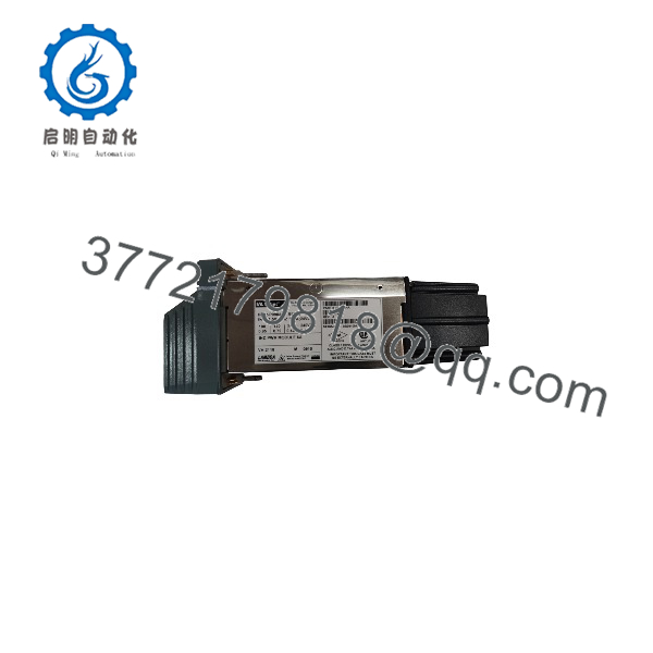
IPM02 P0904HA
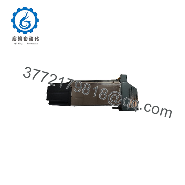
IPM02 P0904HA
Frequently Asked Questions (FAQ)
Q1. What is the Foxboro ?
The is a Foxboro I/A Series DCS power-supply module. Multiple component references explicitly associate with and list it within Foxboro I/A Series system hardware.
Q2. Is the same as ?
Yes, available Foxboro component references identify as . Some inventories write the designation as /, while others use .
Q3. Is the obsolete?
It is a legacy Foxboro I/A Series component, and current market references primarily treat it as a replacement/stock item rather than a current-generation DCS power supply. However, I would not assign a formal OEM lifecycle status without an applicable Foxboro/Schneider Electric lifecycle notice.
Q4. Can I replace with another ?
Do not assume that every item labeled is electrically interchangeable. Verify the complete part number, hardware revision, system configuration, input supply, output rails, and mechanical arrangement. A generic “” match is not enough for a DCS power-supply replacement.
Q5. Will replacing the erase my Foxboro DCS configuration?
The is a power-supply component, not the primary DCS application-logic storage device. Replacing the power supply therefore should not be treated like replacing a CP processor. However, the controlled system still needs to be placed into the approved maintenance state, and the associated processors and I/O should be checked after power restoration.
Q6. Why is sold at different prices by different suppliers?
Legacy Foxboro components can appear as new old stock, new surplus, refurbished/tested, or used inventory. Those conditions are not equivalent. Ask for the actual unit’s nameplate photograph, serial information, condition statement, test evidence, and warranty terms before comparing quotations.
Q7. What should I send a supplier when requesting ?
Provide “Foxboro , ” plus a photograph of the existing module’s nameplate and connectors. If available, include the I/A Series chassis/rack model and the current power-supply arrangement. That information is much safer than ordering from “” alone.



