 WhatsApp: +86 16626708626
 Email:
 Phone: +86 16626708626
Description
Key Technical Specifications
| Parameter | Value |
|---|---|
| Catalog number | P0916AW |
| Associated FBM | FBM241C |
| Brand | Foxboro / Invensys |
| System platform | Foxboro I/A Series 200 I/O |
| Product type | Termination assembly (TA) |
| Terminal style | Compression terminals |
| Ring-lug equivalent | P0916AX |
| Discrete inputs | 8 contact-sense inputs |
| Input signal range | 15 to 60 V DC |
| Input connection | 2-wire contact or solid-state switch input |
| Discrete outputs | 8 switch outputs |
| Output rating | 30 V DC at 5 A, externally sourced |
| Output protection | Shunt diodes; relay option rated 5 A at 30 V DC |
| Isolation | Channel-to-channel and channel-to-ground isolation; group isolation with external excitation |
| FBM redundancy | Supports FBM-level redundancy when used with a redundant FBM241C pair |
| Mixed-voltage caution | P0916AW/AX supports mixed input/output signal voltages; Foxboro recommends using one signal voltage per assembly and maintaining segregation |
| Compatible mounting | Compact 200 Series FBM baseplate and associated termination-cable arrangement |
| Physical format | DIN-rail or rack-mounted termination assembly |
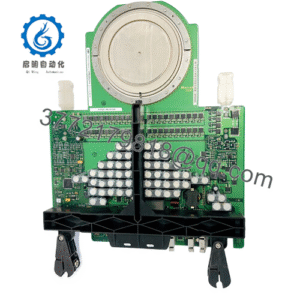
The P0916AW is the compression-terminal termination assembly for the Foxboro FBM241C. It provides eight 15–60 V DC contact-sense inputs and eight externally sourced 30 V DC / 5 A switch outputs; the ring-lug version is P0916AX.
Product Introduction
The Foxboro P0916AW is a termination assembly for the FBM241C channel-isolated discrete I/O module in the Foxboro I/A Series 200 I/O platform. It provides the field-side interface for eight contact-sense inputs and eight switch outputs, allowing field contacts, solid-state switches, and externally powered loads to connect to the FBM.
This assembly is selected when maintaining an existing FBM241C installation with compression-type field wiring. It supports redundant FBM operation when installed with a redundant FBM241C pair, but the input and output voltage classes must be engineered and segregated according to the Foxboro termination-assembly requirements.
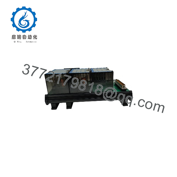
P0916AW
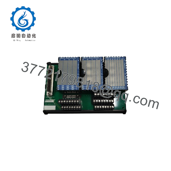
P0916AW
Installation & Configuration Guide
Stage 1: Pre-Installation Preparation
Estimated time: 30–45 minutes.
- ⚠️ Obtain an outage or approved online-maintenance authorization for the affected Foxboro I/A FBM.
- Identify the FBM241C position, termination-assembly location, field circuits, and associated control loops.
- Apply lockout/tagout to field-power circuits feeding the outputs and externally powered contacts.
- For output circuits, verify that actuators, interlocks, and downstream loads are in a safe state.
- Prepare an ESD wrist strap, insulated screwdrivers, multimeter, torque screwdriver, wire labels, ferrules or ring lugs as applicable, and a camera.
- Photograph the existing P0916AW terminal numbering, field wiring, shields, jumpers, and FBM/baseplate position.
- Export or record the FBM241C configuration, channel descriptions, alarm limits, and associated control-logic references.
⚠️ Do not mix 15–60 V DC contact-sense inputs and 30 V DC / 5 A outputs without confirming the original design. Foxboro recommends using one signal voltage per termination assembly and maintaining segregation.
Stage 2: Removing the Old Termination Assembly
Estimated time: 20–30 minutes.
- De-energize the FBM241C field-power circuits and verify 0 V at the termination assembly.
- Disable or place the associated FBM in a safe maintenance state according to the Foxboro I/A procedure.
- Label every input, output, common, shield, and externally sourced power conductor.
- Disconnect field wiring from the compression terminals; do not cut or reuse damaged conductors without re-terminating them.
- Release the termination-assembly mounting hardware.
- Remove the P0916AW from the Compact 200 Series baseplate or mounting arrangement.
- Inspect the FBM connector area, baseplate connectors, cable shields, and terminal housings for damage, contamination, or overheating.
⚠️ Keep the removed P0916AW until the replacement has passed input, output, and FBM communication checks.
Stage 3: Installing the New Termination Assembly
Estimated time: 20–30 minutes.
- Verify the replacement is Foxboro P0916AW, the compression-terminal version for FBM241C. Do not substitute P0916AX unless the field wiring uses ring-lug terminations.
- Put on an ESD wrist strap before handling the FBM or termination assembly.
- Mount the P0916AW in the same location and orientation as the original.
- Reconnect labeled input, output, common, externally sourced power, and shield wiring.
- Torque compression terminals to the specified value; verify that no stray strands protrude.
- Confirm output shunt-diode or relay-protection arrangements match the original design.
- Reconnect the FBM241C and verify that the module and termination assembly are fully seated.
Self-checklist:
- Correct P0916AW compression-style assembly confirmed
- FBM241C compatibility confirmed
- Input voltage class matches 15–60 V DC design
- Output source voltage and current rating verified
- Field wiring labeled and torqued
- Shields and grounds restored
- FBM redundancy arrangement preserved
Stage 4: Power-On & Testing
Estimated time: 1–2 hours.
- ⚠️ Before applying field power, check for shorts between field power, outputs, commons, and earth.
- Restore the FBM241C and termination-assembly field power according to the approved startup sequence.
- Confirm FBM status, fieldbus A/B communication status, and module health.
- Test each of the eight contact-sense inputs using a controlled contact closure or verified field signal.
- Test each of the eight outputs only with loads isolated or in a safe state.
- Verify output voltage, current capability, fuse/protection coordination, and shunt-diode/relay behavior.
- Confirm FBM redundancy by testing the active/standby path if the installation uses a redundant FBM241C pair.
- Restore normal operation only after all input, output, alarm, and communication checks are documented.
⚠️ If an output channel fails to operate, verify the external 30 V DC source, fuse, wiring polarity, shunt diode, FBM configuration, and field-device load before replacing the termination assembly.
Frequently Asked Questions (FAQ)
Is the Foxboro P0916AW an FBM module?
No. It is the termination assembly for an FBM241C module. The FBM241C is the electronic I/O module; the P0916AW provides the field-side compression-terminal interface.
What is the difference between P0916AW and P0916AX?
They provide the same FBM241C input/output termination function, but P0916AW uses compression terminals and P0916AX uses ring-lug terminals. Choose the version that matches the installed field-wiring termination style.
What input voltage does P0916AW support?
The eight contact-sense inputs accept 15 to 60 V DC signals from contacts or solid-state switches.
What can the outputs drive?
The eight outputs are externally sourced switch outputs rated 30 V DC at 5 A. Verify the external power supply, protective device, and load inrush/current requirements before connecting actuators.
Can I use one P0916AW for mixed input and output voltages?
Technically, the FBM241C/P0916AW arrangement supports mixed signal voltages, but Foxboro recommends using one signal voltage per assembly and maintaining segregation. For new work, avoid mixed-voltage wiring unless the original design specifically requires it.
Can I hot-swap the FBM241C with this termination assembly installed?
Foxboro’s 200-series FBM modules support hot-swap operation, but the termination assembly and field wiring must remain correctly connected and protected. Follow the site’s approved I/A maintenance procedure and verify redundancy behavior before replacing a module.
Why does the P0916AW cost more than a basic terminal block?
It is a Foxboro-engineered FBM241C termination assembly with defined channel isolation, output protection, redundancy support, and I/A-compatible mechanical/electrical interfaces—not a generic terminal block.