
 WhatsApp: +86 16626708626
 Email:
  Phone: +86 16626708626
Description
Key Technical Specifications
| Parameter | Value |
|---|---|
| Model | PBCO-D8-010 |
| Product Type | 8-Position Termination Board |
| Compatible Systems | Foxboro I/A Series DCS |
| Compatible FBM Modules | FBM201, FBM204, FBM205, FBM237 |
| Supported Configurations | 8 AI, 8 AO, or 4 AI + 4 AO |
| Supply Voltage | 24 VDC nominal (20–30 VDC) |
| Power Supply | Redundant with OR-diode redundancy |
| Reverse Polarity Protection | Yes |
| Protection Fuse | 2 A time-delay fuse |
| I/O Interface | Two 25-pin SUB-D male connectors |
| Field Wiring | Polarized plug-in screw terminal blocks (up to 2.5 mm²) |
| LED Indicators | Green: Power, Red: Fault |
| Fault Output | Volt-free SPDT relay contact |
| Operating Temperature | −20 °C to +60 °C |
| Relative Humidity | Up to 90% non-condensing |
| Mounting | Surface mounting |
| Weight | Approximately 960 g |
| Installation Area | Safe Area (Non-Hazardous Location) |
Product Introduction
The Foxboro PBCO-D8-010 is an 8-position termination board developed for Foxboro I/A Series fieldbus modules. It provides a direct interface between compatible FBM201, FBM204, FBM205, and FBM237 I/O cards and intrinsically safe isolation modules, eliminating the need for a conventional Field Termination Assembly in many installations.
Designed for process automation systems in the oil and gas, chemical, power generation, and pharmaceutical industries, the PBCO-D8-010 incorporates redundant 24 VDC power inputs, onboard fault monitoring, integrated shield grounding, and plug-in terminal blocks that simplify installation and maintenance. Before installation, always verify the installed FBM type and wiring configuration to ensure compatibility.
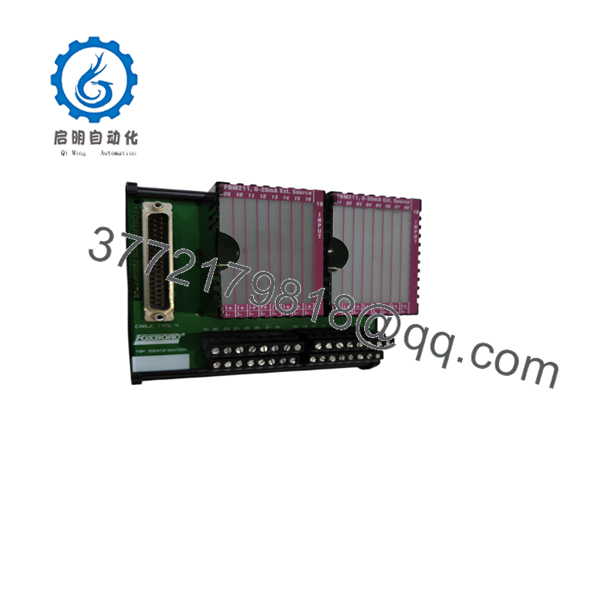
PBCO-D8-010
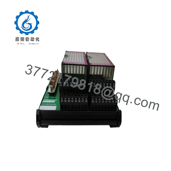
PBCO-D8-010
Installation & Configuration Guide
Stage 1 – Pre-Installation Preparation (10 Minutes)
⚠️ Safety First
- Notify operations of the planned shutdown.
- Place the process in a safe operating state.
- Perform Lock-Out/Tag-Out (LOTO).
- Remove cabinet power and allow at least 5 minutes for discharge.
Required Tools
- ESD wrist strap
- Phillips screwdriver
- Digital multimeter
- Wire labels
- Smartphone or camera
- Torque screwdriver
Preparation
- Record the installed FBM module number.
- Back up the DCS configuration if applicable.
- Photograph all field wiring.
- Verify the replacement board is PBCO-D8-010.
Stage 2 – Removing the Existing Board (10 Minutes)
- Disconnect both redundant 24 VDC power supplies.
- Label every field cable.
- Remove the two SUB-D interface cables.
- Disconnect the plug-in terminal blocks.
- Remove the mounting hardware.
- Inspect connectors, shield rail, and grounding points.
⚠️ Keep the original board until the replacement has passed all commissioning tests.
Stage 3 – Installing the Replacement (10 Minutes)
- Wear an ESD wrist strap.
- Secure the replacement board.
- Connect the protective earth.
- Connect both redundant power supplies.
- Reconnect the SUB-D interface cables.
- Reinstall all field wiring according to the original documentation.
- Verify that the 2 A protection fuse is installed.
Installation Checklist
- ☑ Correct model verified
- ☑ Earth connected
- ☑ Power polarity confirmed
- ☑ SUB-D connectors secured
- ☑ Terminal blocks locked
- ☑ Shield connections verified
Stage 4 – Power-Up & Commissioning (10 Minutes)
- Verify no short circuits exist on the 24 VDC supply.
- Apply power.
- Confirm the green Power LED is illuminated.
- Verify the red Fault LED remains off.
- Confirm communication with the connected Foxboro FBM modules.
- Perform loop testing for every configured analog channel.
⚠️ Troubleshooting: If the fault relay remains energized or the red LED stays on, first inspect the power supply voltage, fuse, FBM interface cables, and field wiring before replacing the board.
Frequently Asked Questions (FAQ)
Q1. Which Foxboro FBM modules are compatible with the PBCO-D8-010?
The board supports FBM201, FBM204, FBM205, and FBM237. Depending on the installed FBM, it can be configured for 8 analog inputs, 8 analog outputs, or a mixed 4 AI + 4 AO arrangement.
Q2. Does the board support redundant power?
Yes. It accepts dual 24 VDC power inputs and uses OR-diode circuitry for automatic redundancy while providing reverse-polarity protection.
Q3. Can the PBCO-D8-010 be installed in a hazardous area?
No. The termination board is intended for installation in the safe (non-hazardous) area. Hazardous-area protection is achieved through compatible intrinsic safety isolation modules connected to the board.
Q4. Is this a direct replacement for a standard Foxboro Field Termination Assembly?
For supported FBM modules, yes. The is designed to interface directly with the Foxboro I/O cards using standard system cables, reducing additional field termination hardware. Always verify cable compatibility before replacement.
Q5. What should I verify before ordering?
Confirm the following:
- Exact model number ()
- Installed FBM module type
- Required AI/AO channel configuration
- System cable type
- Power supply arrangement
- Intrinsic safety module configuration
Verifying these details before purchase helps avoid commissioning delays and wiring modifications.



