
 WhatsApp: +86 16626708626
 Email:
  Phone: +86 16626708626
Description
3. Key Technical Specifications
| Parameter | Value |
|---|---|
| Manufacturer | GE Multilin |
| Model | 339-E-P5-G5-H-E-S-N-N-SN-D-N |
| Product Type | Digital Motor Protection Relay |
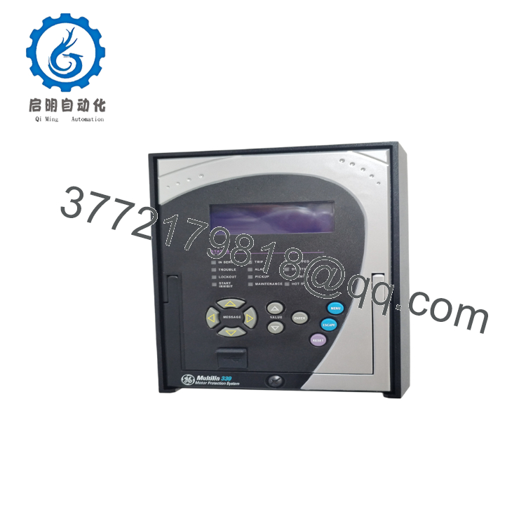
| Series | Multilin 339 |
| Phase CT Inputs | 5 A |
| Ground CT Input | 5 A |
| Control Power | 125–250 VDC / 120–240 VAC (High Voltage Supply) |
| Digital Inputs | 10 Contact Inputs |
| Relay Outputs | 2 Form A + 5 Form C |
| Communications | Front USB, Rear RS485 (Modbus RTU, DNP3, IEC 60870-5-103) |
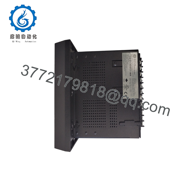
| Mounting | Drawout Case Design |
| Configuration Software | GE EnerVista Setup |
| Typical Application | Medium-voltage motor protection and control |
| Operating Functions | Thermal overload, phase loss, ground fault, locked rotor, undercurrent, overcurrent, stall protection |
| Standards | IEC-based motor protection functions and industrial protection applications |
4. Product Introduction
The GE Multilin 339-E-P5-G5-H-E-S-N-N-SN-D-N is a digital motor protection relay designed for low- and medium-voltage motor applications requiring comprehensive protection, monitoring, control, and diagnostics. It belongs to the proven Multilin 339 family widely used in mining, water treatment, oil and gas, utilities, and heavy manufacturing.
This configuration provides 5 A phase and ground current inputs, a high-voltage universal control power supply, standard communications through USB and RS485, and a drawout chassis for easier maintenance. Configuration and commissioning are performed using GE EnerVista software, allowing engineers to manage protection settings, event records, and diagnostics efficiently.
5. Installation & Configuration Guide
Stage 1 – Pre-Installation Preparation (10 Minutes)
⚠️ Safety First
- Notify operations personnel of scheduled downtime.
- Lock out and tag out all control and motor power sources.
- Wait at least 5 minutes for internal capacitors to discharge.
- Verify zero voltage using a calibrated multimeter.
Required Tools
- ESD wrist strap
- PH1 screwdriver
- Digital multimeter (Fluke 115 or equivalent)
- Wire labels
- Smartphone for wiring documentation
- Laptop with GE EnerVista software
Data Backup
- Export existing relay settings.
- Save event records.
- Record firmware revision.
- Photograph every terminal connection.
- Photograph any jumper or switch configuration.
Stage 2 – Removing the Existing Relay (5 Minutes)
- Remove the front cover.
- Label every field wire.
- Disconnect wiring without applying excessive force.
- Release the drawout locking mechanism.
- Pull the relay straight out.
⚠️ Do not discard the old relay until the replacement has been fully commissioned.
Inspect:
- Bent backplane pins
- Dust accumulation
- Connector damage
- Loose terminal screws
Stage 3 – Installing the New Relay (10 Minutes)
- Wear an ESD wrist strap.
- Verify the complete model number matches:
339-E-P5-G5-H-E-S-N-N-SN-D-N - Install the relay into the drawout chassis.
- Ensure the locking mechanism fully engages.
- Reconnect all wiring according to the photographs.
- Restore communication wiring.
- Import or manually restore the saved configuration.
Self-Checklist
- ☑ Correct model installed
- ☑ Wiring verified
- ☑ CT polarity confirmed
- ☑ Communications connected
- ☑ Relay fully seated
- ☑ Ground connection verified
Stage 4 – Power-Up & Commissioning (10 Minutes)
Before Energizing
- Verify no shorts on the control power circuit.
- Confirm CT circuits remain properly terminated.
Commissioning Steps
- Apply control power only.
- Verify normal LED startup.
- Connect using EnerVista.
- Confirm firmware version.
- Load the saved settings if required.
- Verify communications with the PLC or SCADA.
- Inject test current.
- Confirm relay operation.
- Verify all output contacts.
- Test motor trip logic before returning the motor to service.
⚠️ Troubleshooting
Solid ERR LED
- Firmware mismatch
- Corrupted settings
- Hardware fault
No Communications
- Incorrect RS485 address
- Incorrect baud rate
- Wiring polarity reversed
- Modbus settings inconsistent

- 339-E-P5-G5-H-E-S-N-N-SN-D-N
- 339-E-P5-G5-H-E-S-N-N-SN-D-N
6. Frequently Asked Questions (FAQ)
Q1. Can this relay be hot-swapped?
No. Although the drawout design simplifies maintenance, GE recommends isolating control power before removing the relay. Removing it under power may interrupt protection functions and can damage the backplane or connected equipment.
Q2. Is this model obsolete?
The Multilin 339 family is a mature product line and may be considered legacy equipment in many installations. New surplus inventory is still available from specialized industrial automation suppliers, but availability is becoming more limited.
Q3. Will I lose my relay settings during replacement?
Not if you’ve backed them up beforehand. Always export the configuration with GE EnerVista before removing the original relay. If no backup exists, you may need to manually recreate the protection settings from commissioning records.
Q4. What should I check before ordering?
Verify:
- Complete catalog number
- CT secondary rating (1 A vs. 5 A)
- Control power voltage
- Communication option
- Drawout or non-drawout case
- Firmware compatibility with the existing protection scheme
Ordering only by the “339” series number is a common source of installation delays.
Q5. What is the most common installation mistake?
The most frequent issue is replacing the relay without documenting the existing configuration. I’ve seen maintenance crews spend an entire shift troubleshooting communication failures that were ultimately caused by an incorrect RS485 address or modified protection settings. Taking photos and backing up the configuration before removal typically prevents most commissioning problems.
Q6. Why is your price lower than the OEM list price?
Many industrial automation suppliers stock new surplus inventory purchased through excess project stock, plant closures, or distributor overstock. These products are genuine OEM hardware but are often available below the original manufacturer list price. Always confirm the unit’s condition, warranty, and functional test documentation before purchase.
Q7. What quality inspections should be performed before shipment?
A thorough inspection should include:
- OEM label and serial number verification
- Visual inspection for corrosion, scratches, or repair marks
- Power-on self-test
- Communication verification using EnerVista
- Digital input/output functional testing
- Insulation resistance testing (>10 MΩ at 500 V where applicable)
- Firmware version documentation
- Final QC inspection
- ESD-safe packaging with protective cushioning
Test reports, photographs, and functional verification records should be retained and provided upon request for complete traceability.



