
 WhatsApp: +86 16626708626
 Email:
  Phone: +86 16626708626
Description
Order Code Configuration
| Code | Description |
|---|---|
| 369 | Base Motor Management Relay |
| HI | 50–300 VDC / 60–265 VAC control power |
| 0 | No optional RTD inputs |
| M | Optional metering package |
| 0 | No fiber optic port |
| 0 | No optional communication protocol card |
| 0 | Standard environment (no harsh environment coating) |
| E | Enhanced diagnostics and enhanced faceplate |
The ordering code matches GE Multilin’s official configuration guide.
3. Key Technical Specifications
| Parameter | Value |
|---|---|
| Manufacturer | GE Multilin |
| Model | 369-HI-0-M-0-0-0-E |
| Product Type | Digital Motor Management Relay |
| Series | Multilin 369 |
| Control Power | 50–300 VDC / 60–265 VAC |
| Metering Package | Included (Option M) |
| RTD Inputs | None (0 Option) |
| Fiber Optic Port | Not Installed |
| Protocol Interface | Standard Serial Communications |
| Front Port | RS232 Programming Port |
| Rear Communications | RS485 (Modbus RTU) |
| Display | LCD with Enhanced Faceplate |
| Protection Functions | Thermal overload, stall, locked rotor, phase loss, current unbalance, ground fault |
| Mounting | Panel Mount (Non-drawout) |
| Approximate Dimensions | 296 × 107 × 205 mm |
| Approximate Weight | 4.5 kg (10 lb) |
The Multilin 369 product has been discontinued by GE Vernova. The recommended current-generation replacement platform is the Multilin 859 Motor Protection System.
4. Product Introduction
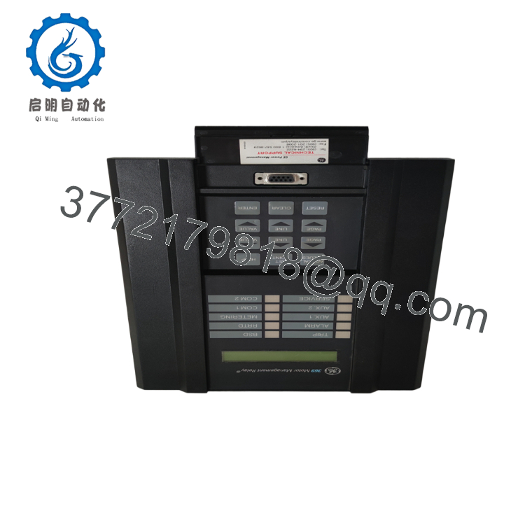
The GE Multilin 369-HI-0-M-0-0-0-E is a digital motor management relay designed to protect, monitor, and control medium-voltage and large low-voltage AC motors. It combines motor protection algorithms, operational monitoring, event recording, and diagnostic capabilities into a single protection relay suitable for critical industrial applications.
This configuration includes the HI universal control power supply, the optional metering package (M), and Enhanced Diagnostics (E). These options provide voltage, power, and energy metering, Motor Health Reports, enhanced event recording, and expanded diagnostics for maintenance personnel. Although the 369 is now a legacy product, it remains widely deployed in power generation, mining, water treatment, petrochemical, and heavy manufacturing facilities.

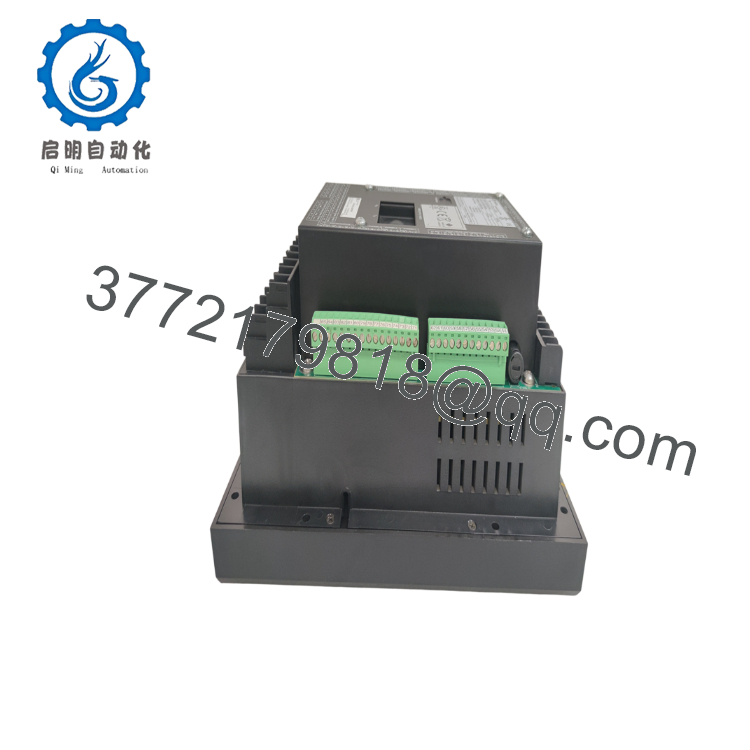
- 369-HI-0-M-0-0-0-E
- 369-HI-0-M-0-0-0-E
5. Installation & Configuration Guide
Stage 1 – Pre-Installation Preparation (10 Minutes)
⚠️ Safety First
- Notify plant operations before removing motor protection.
- Lock out and tag out all motor feeders.
- Isolate relay control power.
- Wait at least 5 minutes before handling the relay.
- Verify zero voltage with a calibrated multimeter.
Tools Required
- ESD wrist strap
- PH1 screwdriver
- Fluke 115 multimeter
- Wire markers
- Smartphone for wiring documentation
- Laptop with GE EnerVista 369 Setup software
Data Backup
- Export all relay settings.
- Save event records and oscillography.
- Record firmware revision.
- Photograph all terminal wiring.
- Document communication settings and Modbus address.
Stage 2 – Removing the Old Relay (5 Minutes)
- Remove the front panel if necessary.
- Label every field wire.
- Disconnect terminal blocks carefully.
- Remove mounting hardware.
- Pull the relay straight out without twisting.
⚠️ Do not dispose of the original relay until commissioning is complete.
Inspect:
- Terminal condition
- Dust contamination
- Loose wiring
- Signs of overheating
Stage 3 – Installing the New Relay (10 Minutes)
- Wear an ESD wrist strap.
- Verify the complete catalog number:
369-HI-0-M-0-0-0-E - Mount the relay securely.
- Reconnect all wiring according to the documented layout.
- Restore communication wiring.
- Load the saved configuration using EnerVista.
- Verify CT and control power connections.
Self-Checklist
- ☑ Model number verified
- ☑ Wiring secure
- ☑ CT polarity confirmed
- ☑ Communication settings restored
- ☑ Protective earth connected
Stage 4 – Power-On & Testing (10–15 Minutes)
Pre-Power Check
- Verify insulation resistance where applicable.
- Confirm there are no control power shorts.
- Check CT secondary circuits before energizing.
Commissioning Steps
- Apply control power.
- Observe the startup sequence.
- Confirm normal RUN status.
- Connect with EnerVista software.
- Verify firmware revision.
- Restore relay settings if required.
- Test Modbus communications.
- Inject secondary current to verify protection.
- Confirm alarm and trip outputs.
- Return the protected motor to service after successful functional testing.
⚠️ Troubleshooting Note
Relay fails to communicate
- Verify RS485 polarity.
- Confirm Modbus address and baud rate.
- Check firmware compatibility.
Unexpected protection trips
- Review CT ratio configuration.
- Verify thermal model settings.
- Confirm motor full-load current parameters.
6. Frequently Asked Questions (FAQ)
Q1. Can the GE 369-HI-0-M-0-0-0-E be hot-swapped?
No. The Multilin 369 is not designed for hot swapping. Removing the relay under power can interrupt motor protection and may damage connected equipment.
Q2. Is this relay obsolete?
Yes. GE Vernova has classified the Multilin 369 as a legacy product and recommends the Multilin 859 as its successor. However, many facilities continue to operate the 369 because of its proven reliability and installed base.
Q3. What advantages does the “M” option provide?
The Metering Package (M) adds voltage, power, energy, frequency, and additional analog output capabilities. It also enables more comprehensive operational monitoring for maintenance and energy management.
Q4. What features are included with the “E” option?
The Enhanced Diagnostics (E) option includes:
- Enhanced faceplate with motor status indicators
- Motor Health Report
- Enhanced learned motor data
- Motor Start Data Logger
- Enhanced event recorder
- Security audit trail
These features simplify troubleshooting and maintenance planning.
Q5. Will replacing the relay erase my settings?
No, provided you export the configuration before removal. Always create a complete backup with GE EnerVista and document communication parameters before installing the replacement unit.
Q6. Why are new surplus units available if the product is discontinued?
Many new surplus units originate from canceled projects, distributor excess inventory, or unused plant spare parts. These genuine OEM products are often available long after factory production has ended, making them valuable for maintaining legacy systems.
Q7. What quality inspections should be completed before shipment?
A comprehensive inspection should include:
- OEM serial number verification
- Visual inspection for corrosion, scratches, and repair marks
- Power-on self-test
- LCD and keypad verification
- RS232 and RS485 communication testing
- Relay output verification
- Firmware version documentation
- Insulation resistance testing (where applicable)
- Final QC approval
- ESD-safe packaging with anti-static protection
For planned shutdowns, requesting a functional test report and firmware verification before shipment helps reduce commissioning time and minimizes the risk of compatibility issues.



