
 WhatsApp: +86 16626708626
 Email:
  Phone: +86 16626708626
Description
3. Key Technical Specifications
| Parameter | Value |
|---|---|
| Manufacturer | GE |
| Model | 369B1860G0030 |
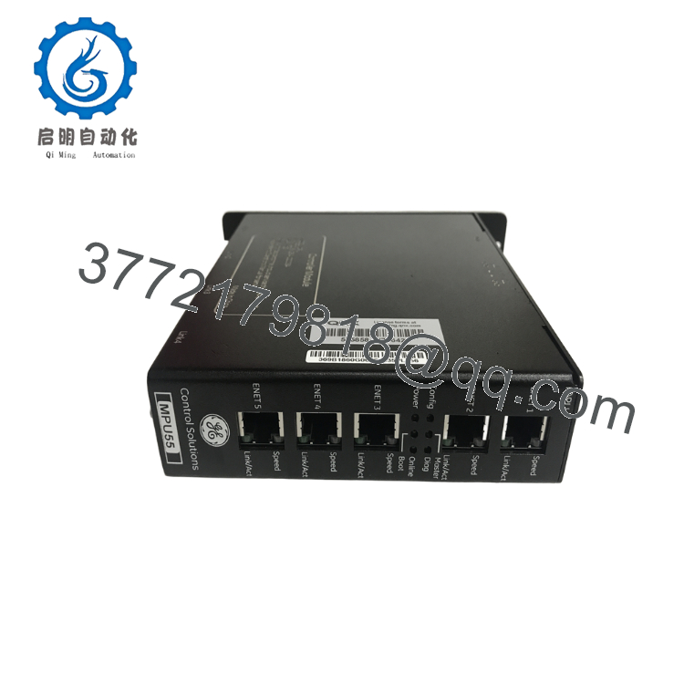
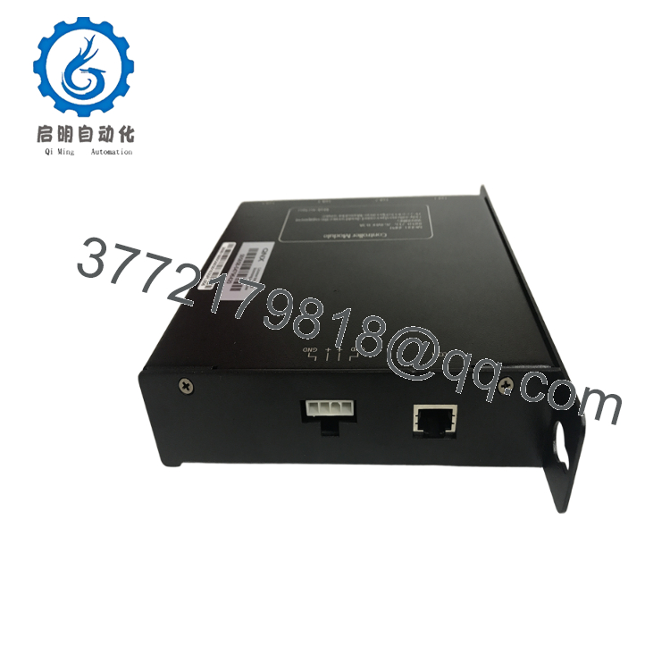
| Product Type | MPU55 Nexus Controller Module |
| Platform | GE Nexus / MPU55 |
| Processor | High-performance embedded processor |
| Memory | Industrial control memory architecture |
| Communication Interfaces | Ethernet, Modbus, industrial serial communications (configuration dependent) |
| Installation | Rack-mounted controller module |
| Diagnostic Features | LED status indication and onboard diagnostics |
| Operating Environment | Industrial control cabinets |
| Typical Applications | Turbine control, power generation, DCS/PLC integration |
| Configuration | System software dependent |
| Condition | New Original or Tested New Surplus |
GE does not publicly publish a complete datasheet for this exact catalog number. Interface options and firmware should be verified against the installed system before replacement.
4. Product Introduction
The GE 369B1860G0030 is an MPU55 Nexus Controller Module used in GE industrial automation and turbine control systems. It serves as the primary processing unit responsible for executing control logic, coordinating communications, and managing system data within a distributed control architecture.
This controller is typically installed in power generation and process automation environments where high system availability and deterministic control are required. Before installation, engineers should verify firmware compatibility, system configuration, and hardware revision to maintain compatibility with the existing control platform.
5. Installation & Configuration Guide
Stage 1 – Pre-Installation Preparation (10 Minutes)
⚠️ Safety First
- Notify operations before shutting down the control system.
- Perform Lock-Out/Tag-Out (LOTO).
- Disconnect control power.
- Wait at least 5 minutes for stored energy to dissipate.
- Verify zero voltage using a calibrated multimeter.
Required Tools
- ESD wrist strap
- Phillips screwdriver
- Fluke 115 (or equivalent) multimeter
- Wire labels
- Smartphone for documentation
- Engineering laptop with the appropriate GE configuration software
Data Backup
- Back up controller configuration.
- Save application files and system database.
- Record firmware version.
- Photograph wiring and module location.
- Document network configuration and IP addresses.
Stage 2 – Removing the Existing Module (5 Minutes)
- Remove the cabinet cover if required.
- Label all communication and power cables.
- Disconnect connectors carefully.
- Release module retaining clips.
- Remove the controller using straight extraction to avoid connector damage.
⚠️ Keep the original module until the replacement has completed commissioning successfully.
Inspect:
- Backplane connectors
- Bent pins
- Dust contamination
- Connector wear
Stage 3 – Installing the New Module (10 Minutes)
- Wear an ESD wrist strap.
- Confirm the complete catalog number:
369B1860G0030 - Verify hardware revision compatibility.
- Insert the module evenly into the rack.
- Lock retaining hardware.
- Reconnect all cables.
- Restore the controller configuration.
- Verify communication settings before energizing.
Installation Checklist
- ☑ Correct model installed
- ☑ Firmware compatibility confirmed
- ☑ Wiring verified
- ☑ Communication ports connected
- ☑ Module fully seated
- ☑ Grounding confirmed
Stage 4 – Power-Up & Commissioning (10–15 Minutes)
Before Applying Power
- Check the control power supply.
- Verify connector seating.
- Inspect for short circuits.
Commissioning Procedure
- Energize the controller rack.
- Observe LED startup sequence.
- Confirm normal RUN indication.
- Connect using the engineering workstation.
- Verify firmware revision.
- Download the backed-up configuration if required.
- Verify network communications.
- Confirm I/O exchange with field devices.
- Monitor diagnostics for faults.
⚠️ Troubleshooting
RUN LED does not illuminate
- Verify power supply
- Check module seating
- Inspect the backplane
Communication Failure
- Verify IP address
- Confirm firmware compatibility
- Check Ethernet or serial configuration
- Inspect network cabling

- 369B1860G0030
- 369B1860G0030
6. Frequently Asked Questions (FAQ)
Q1. Can the GE 369B1860G0030 be replaced while the system is energized?
No. This controller is not intended for hot swapping. Removing it under power can interrupt the control system and may damage the backplane or corrupt controller operation.
Q2. Is this module still available as new?
Most units available today are new surplus or unused OEM inventory. Availability varies because this is a specialized industrial controller rather than a current high-volume product.
Q3. Will replacing the controller erase my application?
Not if the application and configuration have been backed up beforehand. Always save the controller database, firmware information, and configuration files before removing the original module.
Q4. What should I verify before ordering?
Check:
- Full catalog number (369B1860G0030)
- Hardware revision
- Firmware version
- Installed GE control platform
- Communication interface requirements
- Rack compatibility
Matching only the base part number is often insufficient for legacy GE control systems.
Q5. What is the most common replacement issue?
Firmware mismatch is the issue encountered most frequently. A controller with a different firmware revision may boot normally but fail to synchronize with the remaining control network. Record the existing firmware version before removing the original module whenever possible.
Q6. Why are new surplus units typically less expensive than OEM factory pricing?
New surplus inventory generally originates from canceled projects, distributor excess stock, or plant inventory reductions. These are genuine OEM components but are sold through the secondary industrial automation market rather than directly by the original manufacturer.
Q7. What quality inspections should be completed before shipment?
A comprehensive inspection should include:
- OEM part number and serial number verification
- Visual inspection for corrosion, impact damage, or repair marks
- Power-on functional verification
- Communication interface testing
- Firmware identification and documentation
- Insulation and grounding checks where applicable
- Final QC approval
- ESD-safe packaging with protective cushioning
For critical shutdown projects, requesting test reports, startup photographs, and firmware verification records before shipment can significantly reduce commissioning risk.



