
 WhatsApp: +86 16626708626
 Email:
  Phone: +86 16626708626
Description
Key Technical Specifications
| Parameter | Value |
| Control Power Input (HI Option) | 70–265 VAC (50/60 Hz) / 90–300 VDC |
| Phase Current Inputs (P5 Option) | 5 A secondary three-phase CT configuration |
| Analog Outputs (A20 Option) | Four isolated 4–20 mA analog outputs (assignable) |
| Chassis Mechanical Option (E) | Enhanced diagnostic faceplate with environmental protection coating |
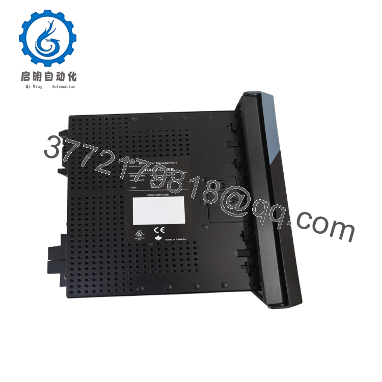
| Enclosure System | SR469-CASE standard drawout cutout matching rear terminal connections |
| RTD Inputs | 12 channels (100 \Omega Platinum, 100 \Omega Nickel, 120 \Omega Nickel, 10 \Omega Copper) |
| Communication Ports | 1 front RS232 panel port, 2 rear RS485 channels running Modbus RTU |
| Waveform Capture | Onboard digital oscillography and comprehensive event logging |
| Operating Temperature | −40 to +60 °C (−40 to +140 °F) |
Product Introduction & Supply Chain Strategy
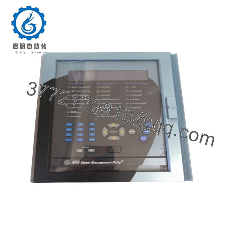
The GE Multilin 469-P5-HI-A20-E paired with the SR469-CASE constitutes a full-featured, microprocessor-based management system engineered for high-horsepower AC motors and critical synchronous machinery. Outfitted with a 5 A phase CT secondary input engine, high-voltage auxiliary power input, and four fully isolated 4–20 mA analog loops, this digital relay handles tracking for thermal models, voltage imbalances, ground faults, and stator/bearing RTD temperature profiles. The drawout case design (SR469-CASE) allows maintenance personnel to slide the internal terminal chassis out for testing or replacement without disturbing the underlying panel wiring array.
Procuring this configuration as New Surplus is an essential step toward minimizing your plant’s Total Cost of Ownership (TCO). Since the 469 product family is a mature legacy line, direct factory replacements are subject to significant lead time variability, risking prolonged stock-out incidents on your primary processing lines. Opting for cheaper refurbished hardware presents significant secondary costs, as aged internal power circuits or worn trip contacts can fail to activate during an overcurrent event, leading to catastrophic motor damage. Keeping an original, factory-sealed surplus assembly on your warehouse shelf ensures your maintenance crew can swap out a failed unit instantly, eliminating downtime while bypassing the high costs of complete system modernization.
Installation & Configuration Guide
Stage 1: Pre-Installation (Prep & Safety)
- Complete full lock-out/tag-out (LOTO) procedures on the primary breaker panel and all auxiliary voltage transformer fuses associated with the slot.
- Fasten a grounded ESD wrist strap to your arm and attach it to an unpainted metal section of the panel enclosure framework before touching the equipment.
- Access the active relay through the front panel port or terminal connection using EnerVista 469 Setup software. Save a copy of the current setpoint parameters, custom protection curves, and calibration maps.
- Verify that external current transformer (CT) shorting blocks are closed tightly to bridge the paths securely. An open-circuit CT on a live circuit will generate high-voltage terminal arcs.
Stage 2: Removal
- Unlatch the front door assembly of the SR469-CASE to reveal the drawout release levers.
- Pull the drawout levers outward to unlock the internal relay chassis mechanism from the primary rear terminal plug connections.
- Slide the relay core carefully forward out of the case housing, keeping the unit level to avoid scratching the internal alignment rails.
- If replacing the entire outer container structure, label and disconnect the rear terminal block wire paths before unbolting the case frame from the cutout panel.
Stage 3: Installation (Clone & Seat)
- Mount the new surplus SR469-CASE into the standard panel cutout gap if a full frame replacement is required. Tighten the perimeter mounting bolts to achieve a flush, dust-tight seal against the panel face.
- Reconnect all rear terminal block wiring lines exactly as noted on your system prints, and torque the screws to 1.0 N·m (9 lb·in) to secure them against machinery vibrations.
- Align the new surplus 469-P5-HI-A20-E inner relay module with the case tracks, then guide it slowly inward until the drawout levers begin to engage the frame.
- Lock the release levers inward completely to establish solid contact between the rear terminal plugs and the case block.
Stage 4: Power-On & Testing
- Disconnect or isolate the primary motor contactor loops, leaving only the auxiliary low-voltage power circuit operational.
- Turn on the auxiliary control power rail (70–265 VAC / 90–300 VDC). Verify the front alphanumeric display panel lights up and stabilizes into a normal “Stopped” or “Ready” condition message.
- Upload your saved setpoint template file via the EnerVista package, and cross-check that the active current scaling values match your actual CT nameplate ratios.
- Initiate an automated safety chain relay trip check via the control software utility options to confirm that the outputs cycle properly before returning the motor to service.

- 469-P5-HI-A20-E SR469-CASE
- 469-P5-HI-A20-E SR469-CASE
Firmware/Software Versions & Upgrade Notes
The 469-P5-HI-A20-E utilizes internal firmware structures that determine the Modbus communication data register maps used by master SCADA and DCS systems. Replacing an older unit with a different firmware version can disrupt communication handshakes, leaving local operations blind to remote data.
Always check the firmware version printed on the side label of the surplus chassis before executing your initial configuration script. If necessary, use the EnerVista suite to verify register compatibility with your existing automation architecture before putting the unit into active service.
Frequently Asked Questions (FAQ)
Q: Why choose a New Surplus 469 assembly over a cheaper refurbished unit?
A: Refurbished protection equipment introduces real, unmeasured secondary risks. While the front faceplate might look clean, the internal electrolytic power capacitors and small mechanical trip contacts inside a used relay carry logged operational hours, which accelerates component degradation. A failure on a used part can result in $50,000+ of unplanned downtime if a medium-voltage motor burns out without the relay triggering a safety shutoff.
Q: Does the “SR469-CASE” designation mean this product includes both the inner relay and the outer enclosure?
A: Yes. This specific inventory bundle features the complete 469-P5-HI-A20-E internal relay module alongside its matching SR469-CASE outer drawout container. This provides a complete replacement solution for facilities dealing with damaged terminal blocks or physical housing degradation on older control panels.
Q: What do the “P5”, “HI”, and “A20” modifiers specify in this model code?
A: The “P5” means the unit is built for 5 A secondary phase current transformers. The “HI” designates a high-voltage power input option (70–265 VAC / 90–300 VDC). The “A20” option provides four isolated 4–20 mA analog outputs for remote telemetry tracking. These specific sub-codes must match your active engineering prints to ensure drop-in operational compatibility.
Q: Will the programming setup and event logs stay saved in the relay when it is in warehouse storage?
A: Yes. All parameters, protective curve definitions, and historical logs are saved directly to non-volatile onboard EEPROM memory. This data will remain completely intact during years of storage and does not depend on internal battery packs or continuous control power to preserve configuration integrity.
Q: What kind of warranty program protects this specific legacy module?
A: We provide a comprehensive 12-month replacement warranty from your logistics delivery date on this item. This coverage guarantees that your surplus unit will meet or exceed standard OEM functional specifications, giving procurement teams complete peace of mind when backing up older industrial facilities.



