
 WhatsApp: +86 16626708626
 Email:
  Phone: +86 16626708626
Description
3. Key Technical Specifications
| Parameter | Value |
|---|---|
| Manufacturer | GE General Electric |
| Model Number | 531X175SSBAAM3 |
| Product Family | GE 531X / Series Six |
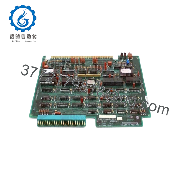
| Functional Description | Dual Channel BIU Interface Board |
| Product Type | Interface PCB Assembly |
| Primary Application | Industrial drive and automation systems |
| Channel Configuration | Dual-channel communication architecture |
| Integrated Circuits | Approximately 47 onboard ICs |
| Diagnostic Indicators | 2 red LEDs |
| Switch Configuration | 1 red toggle switch |
| Jumper Configuration | Multiple configurable jumper ports |
| Connector Type | Edge-card male terminal connector |
| Mounting Method | Rack / chassis-mounted PCB |
| System Compatibility | GE drive control architectures |
| Operating Environment | Industrial electrical cabinet |
| PCB Construction | Industrial-grade conformal-coated board |
| Firmware Dependency | Verify compatibility with installed drive revision |
| Availability | Limited surplus inventory |
| Typical Lead Time | 3–7 business days depending on stock |
The 531X175SSBAAM3 is identified as a GE Dual Channel BIU (Bus Interface Unit) interface board used in industrial drive systems and Series Six control architectures for communication handling and subsystem coordination.
4. Product Introduction
The GE 531X175SSBAAM3 is a Dual Channel BIU interface PCB designed for GE industrial drive systems and Series Six control architectures. The board manages communication between connected control modules and drive subsystems using a dual-channel bus interface configuration.
In operating industrial drive cabinets, interface boards like the 531X175SSBAAM3 are often treated as critical spare components because communication instability between subsystems can shut down entire production lines. Plants maintaining legacy GE drive systems typically retain spare BIU boards onsite to reduce outage duration and avoid complex retrofit work.

- 531X175SSBAAM3
5. Installation & Configuration Guide
Stage 1: Pre-Installation Preparation (Estimated Time: 10 Minutes)
⚠️ Safety First
- Notify operations personnel of the planned downtime.
- Verify all connected drive systems are stopped safely.
- Apply lock out/tag out (LOTO) procedures to incoming cabinet power.
- Wait at least 5 minutes for DC bus capacitors to discharge fully.
Tools Required
- Grounded ESD wrist strap
- PH1 screwdriver
- Fluke 115 multimeter or equivalent
- Wire labels
- Smartphone for cabinet photos
- Flashlight for rack inspection
Data Backup
- Record cabinet slot location and board orientation.
- Photograph:
- Jumper positions
- Toggle switch position
- Connector orientation
- Wiring layouts
- Document existing drive alarms and communication faults.
❗ Photograph everything before removal. I’ve seen engineers lose half a production shift because they forgot one jumper position on an old GE interface board and the communication bus refused to initialize correctly afterward.
Stage 2: Removing the Old Module (Estimated Time: 5–10 Minutes)
- Open cabinet covers carefully.
- Verify incoming cabinet power is fully isolated.
- Label all attached connectors and wiring.
- Release retention clips or mounting hardware.
- Pull the board straight out evenly to avoid edge connector damage.
- Inspect the backplane and connectors for:
- Bent pins
- Oxidation
- Heat discoloration
- Dust accumulation
⚠️ Important Note
Keep the original board nearby during commissioning. Older GE boards often contain site-specific jumper configurations that are not documented anywhere in the cabinet drawings.
Stage 3: Installing the New Module (Estimated Time: 10 Minutes)
Installation Steps
- Wear grounded ESD protection before touching the PCB.
- Verify the exact replacement model number:
- 531X175SSBAAM3
- Compare hardware revision markings carefully.
- Configuration Clone (Crucial):
- Replicate all jumper positions exactly
- Match toggle switch settings
- Verify communication channel configuration
- Align the PCB carefully with the rack guides.
- Insert evenly until fully seated.
- Secure all retention hardware.
- Reconnect all connectors and wiring.
Self-Checklist
- Correct model verified
- Jumpers copied correctly
- Toggle switch matched
- Board fully seated
- Connectors secured
❗ Partial seating causes ugly intermittent faults on these older GE systems. The board may appear powered normally while the communication bus throws random timeout errors every few minutes.
Stage 4: Power-On & Testing (Estimated Time: 15 Minutes)
Pre-Power Check
- Verify no shorts exist on cabinet DC rails.
- Confirm cabinet grounding continuity.
- Inspect for loose tools or hardware inside the cabinet.
Power-On Steps
- Energize the rack or drive cabinet first.
- Observe startup LEDs on the 531X175SSBAAM3.
- Verify communication initializes correctly between connected modules.
- Connect engineering diagnostics if available.
- Check for communication timeout alarms.
- Perform dry-run drive and I/O verification before returning equipment to production.
⚠️ Troubleshooting Note
If communication faults appear immediately after startup:
- Recheck jumper configuration
- Verify full edge-connector seating
- Inspect backplane oxidation
- Confirm proper channel configuration
- Verify firmware and drive revision compatibility
I’ve seen one replacement board trigger intermittent bus faults for nearly two shifts because the jumper configuration defaulted differently from the original factory installation.
Quality Control & Testing Procedure
1. Inbound Inspection & Traceability
Each 531X175SSBAAM3 board undergoes:
- OEM label verification
- Serial number traceability inspection
- Anti-counterfeit checks
- Visual inspection for corrosion, UV yellowing, solder rework, and damaged traces
- Connector and edge-contact inspection
2. Live Functional Testing
Testing is performed using GE-compatible drive hardware whenever available.
Procedures include:
- Controlled power-up testing
- LED startup verification
- Dual-channel communication testing
- Jumper configuration validation
- Continuous energized runtime testing exceeding 24 hours with thermal monitoring
Test photos and startup videos are available upon request.
3. Electrical Parameter Testing
- 500 V insulation resistance testing (>10 MΩ target)
- Ground continuity verification
- Connector continuity checks
- DC rail stability measurement using calibrated Fluke instruments
4. Firmware & Configuration Verification
- Hardware revision documentation
- Jumper and switch configuration recording
- Connector compatibility verification
5. Final QC & Packaging
- QC technician sign-off
- Anti-static ESD bagging
- Shock-resistant bubble wrap packaging
- Heavy-duty corrugated export carton
- QC Passed labeling with inspection date
6. Frequently Asked Questions (FAQ)
Q1: Can the 531X175SSBAAM3 be hot-swapped?
No.
This board participates directly in communication handling between drive subsystems. Pulling it under power can destabilize the communication bus or damage the backplane interface.
Power the cabinet down completely before replacement.
Q2: What exactly does the 531X175SSBAAM3 do?
The 531X175SSBAAM3 functions as a Dual Channel BIU interface board used for communication and coordination between industrial drive system components and control modules.
Q3: Is this model obsolete?
Yes.
The 531X175SSBAAM3 belongs to an older GE drive and Series Six architecture that has been discontinued for years. Most available inventory today comes from surplus stock, strategic plant spares, or tested refurbishment channels.
Q4: Why are jumper settings so important on this board?
Because the jumper configuration affects communication behavior and subsystem routing.
This board contains multiple configurable jumper ports controlling smaller onboard circuits. One incorrect jumper can generate intermittent communication failures that are extremely difficult to troubleshoot.
❗ This is one of the most common mistakes during legacy GE drive maintenance.
Q5: Will replacing this board erase drive parameters or logic?
Normally no.
The board primarily handles communication interface functions. However, older GE systems sometimes rely on hardware-level configuration behavior tied to jumper settings and interface addressing. Always document everything before replacement.
Q6: What is the most common installation mistake?
Incorrect jumper replication and poor connector seating.
I’ve watched technicians spend hours troubleshooting “bad replacement boards” when the actual issue was one misplaced jumper cap or a partially seated edge connector.
Take photos before removal and physically verify seating after installation.
Q7: Why are some 531X175SSBAAM3 boards priced much lower than others?
Usually because of testing and condition differences.
Pricing depends on:
- New surplus versus repaired condition
- Tested versus untested inventory
- Connector condition
- Hardware revision
- Traceability records
- Availability of live functional test data
If a supplier cannot provide actual photos, test documentation, or inspection records, proceed carefully.
Keep these checks in mind and you’ll avoid most of the painful troubleshooting sessions that happen during legacy GE drive system maintenance.


