
 WhatsApp: +86 16626708626
 Email:
  Phone: +86 16626708626
Description
3. Key Technical Specifications
| Parameter | Value |
|---|---|
| Manufacturer | General Electric (GE) |
| Model | 531X301DCCAFG2 |
| Product Type | Drive Control Board |
| Series | GE Mark V Speedtronic |
| Processor | Intel 80186 Microprocessor |
| Memory | EEPROM, Flash, RAM (configuration dependent) |
| Mounting | Rack-mounted printed circuit board |
| Primary Function | Drive control, sequencing, diagnostics |
| Power Source | 125 VDC and/or 120/240 VAC Mark V panel supply |
| Communications | Internal Mark V system bus; configuration-dependent serial interfaces |
| Diagnostics | Built-in self-test, alarm/event logging |
| Typical Applications | Gas turbines, steam turbines, industrial drive control systems |
The board is part of the GE Mark V control platform and functions as a drive control processor responsible for executing control logic, diagnostics, and event logging.
4. Product Introduction
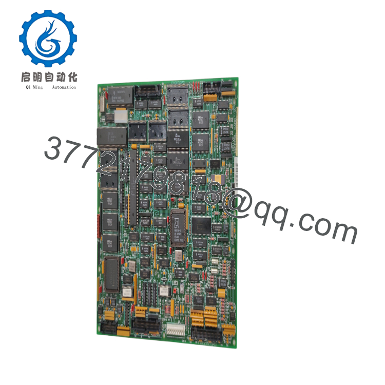
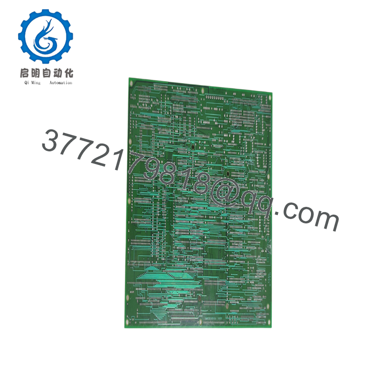
The GE 531X301DCCAFG2 is a Mark V Drive Control Board used in GE Speedtronic turbine and industrial drive control systems. It executes drive control algorithms, coordinates sequencing functions, manages diagnostic routines, and communicates with other processor and I/O boards within the Mark V architecture.
Built around an Intel 80186 processor with EEPROM-based firmware storage, the board provides deterministic control required for turbine and large industrial drive applications. Because the Mark V platform is now a legacy system, replacement boards should always be matched for hardware revision and firmware compatibility before installation.
5. Installation & Configuration Guide
Stage 1 – Pre-Installation Preparation (10 Minutes)
⚠️ Safety First
- Notify operations of the planned shutdown.
- Perform Lock-Out/Tag-Out (LOTO).
- Remove all AC and DC control power.
- Wait at least 5 minutes for capacitor discharge.
- Verify zero voltage using a calibrated multimeter.
Tools Required
- ESD wrist strap
- Phillips screwdriver
- Fluke 115 or equivalent multimeter
- Camera or smartphone
- Engineering workstation
- Anti-static storage bag
Data Backup
- Record the existing firmware revision.
- Back up controller configuration where applicable.
- Photograph board location and cable routing.
- Label every connector before removal.
- Record jumper and switch settings.
Stage 2 – Removing the Old Board (5–10 Minutes)
- Open the Mark V cabinet.
- Confirm all status LEDs are OFF.
- Disconnect ribbon and edge connectors carefully.
- Release retaining hardware.
- Remove the board evenly without twisting.
⚠️ Keep the original board until the replacement has completed all commissioning tests.
Inspect:
- Backplane connectors
- Edge contacts
- Cooling airflow path
- Connector damage
- Dust contamination
Stage 3 – Installing the New Board (10 Minutes)
- Wear an ESD wrist strap.
- Verify the complete part number:
531X301DCCAFG2 - Confirm firmware and hardware revision compatibility.
- Install the board into the correct slot.
- Tighten retaining hardware.
- Reconnect all cables.
- Verify connector seating before energizing.
Installation Checklist
- ☑ Correct part number
- ☑ Firmware compatible
- ☑ All connectors secured
- ☑ Grounding verified
- ☑ Board fully seated
Stage 4 – Power-On & Commissioning (15 Minutes)
Before Applying Power
- Inspect the rack for loose connectors.
- Verify control power supply voltage.
- Check for short circuits.
Commissioning Steps
- Energize the Mark V rack.
- Observe LED startup sequence.
- Confirm processor initialization.
- Verify communication with the HMI.
- Check alarm and event logs.
- Verify I/O communication.
- Perform functional testing of the drive or turbine control system.
- Clear any startup alarms only after identifying their cause.
⚠️ Troubleshooting
Processor does not boot
- Verify firmware device installation.
- Check board seating.
- Confirm rack power supply voltages.
Communication failure
- Verify backplane connector integrity.
- Confirm firmware compatibility.
- Inspect communication daughter boards and internal cables.

- 531X301DCCAFG2
- 531X301DCCAFG2
6. Frequently Asked Questions (FAQ)
Q1. Is the GE 531X301DCCAFG2 still manufactured?
No. The 531X301DCCAFG2 is a legacy GE Mark V component. Most units available today are new surplus, refurbished, or professionally repaired inventory.
Q2. Can this board be hot-swapped?
No. Mark V processor and drive control boards are not hot-swappable. Always remove control power before replacing the board to prevent damage to the backplane and processor circuitry.
Q3. Why is firmware compatibility important?
The onboard EEPROM contains firmware matched to the control system revision. Installing a board with an incompatible firmware version can lead to startup failures, communication faults, or unexpected control behavior. Before replacement, record the firmware revision of the original board and request the same revision if possible.
Q4. What is the most common installation mistake?
The most common issue is reconnecting cables to the wrong connectors after replacement. Although many Mark V connectors appear similar, incorrect placement can prevent the controller from booting or generate multiple I/O faults. Photograph every connection before removal and reconnect one cable at a time.
Q5. Will replacing this board erase the turbine control logic?
Normally, the application software resides within the Mark V control architecture rather than solely on this board. However, firmware and configuration compatibility must be verified before startup. Always create backups and document the existing system configuration before replacement.
Q6. Why are new surplus units available below original OEM pricing?
Most new surplus boards originate from canceled projects, plant modernization programs, or distributor excess inventory. They are genuine OEM components that were never placed into production service and are commonly used to support legacy Mark V installations.
Q7. What quality inspections should be completed before shipment?
A comprehensive quality process should include:
- OEM part number and serial number verification
- Visual inspection for corrosion, damaged traces, or repair marks
- Power-on functional testing in a compatible GE Mark V test rack
- Processor startup verification
- EEPROM firmware identification
- Communication and diagnostic verification
- Electrical inspection of edge connectors
- Final QC approval
- ESD-safe packaging with anti-static shielding and protective cushioning
For planned turbine outages, requesting a functional test report, firmware identification, and board photographs before shipment helps reduce commissioning time and minimizes compatibility risks.



