
 WhatsApp: +86 16626708626
 Email:
  Phone: +86 16626708626
Description
3. Key Technical Specifications
| Parameter | Value |
|---|---|
| Manufacturer | GE Multilin |
| Model | C6M-9UH-00K / UR9CH |
| Product Type | CPU Module |
| Platform | Universal Relay (UR Series) |
| CPU Module | UR9CH |
| Primary Function | Protection, control, monitoring, communications |
| Configuration Software | GE EnerVista UR Setup |
| Communication Support | Ethernet, RS485 (configuration dependent) |
| Supported Protection Functions | Determined by relay firmware and order code |
| Event Recording | Sequence of Events (SOE), fault records, oscillography |
| Mounting | UR Series modular chassis |
| Typical Applications | Feeder, motor, transformer, generator, bus, and line protection systems |
4. Product Introduction
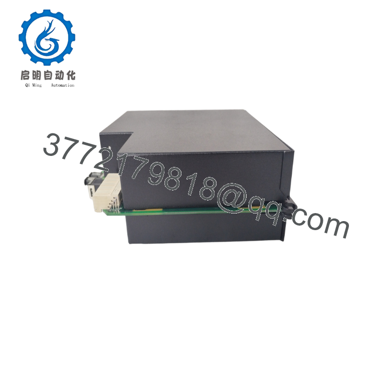
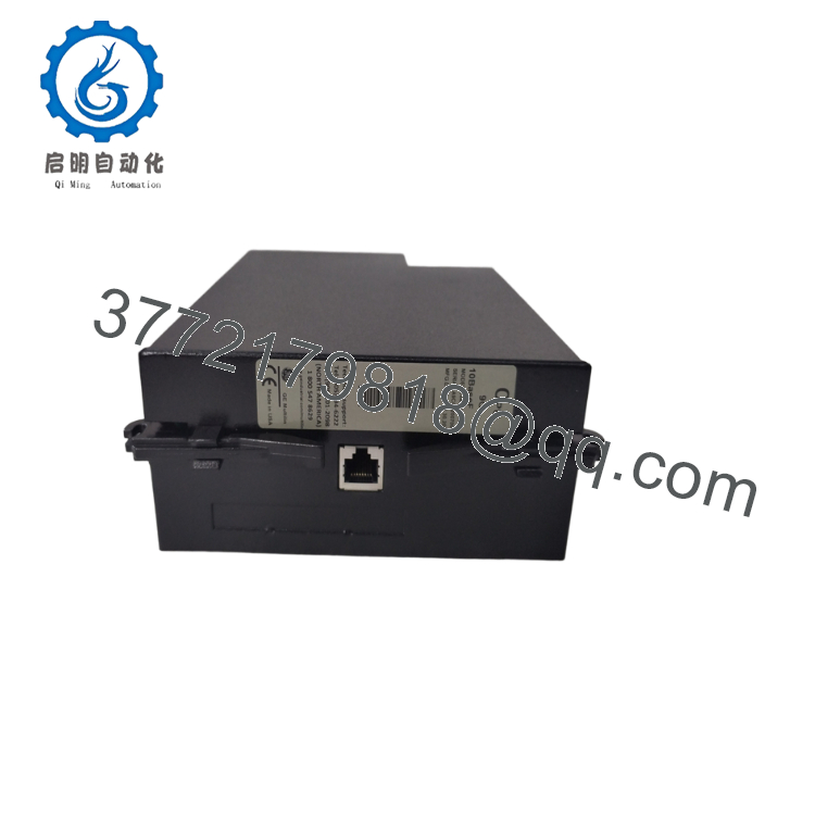
The GE Multilin C6M-9UH-00K UR9CH is a CPU module used in the Universal Relay (UR) Series. It performs the relay’s protection algorithms, manages I/O processing, executes programmable logic, records fault events, and handles communications with SCADA, DCS, and engineering workstations.
The UR9CH processor is designed for high-speed protection applications where dependable operation and deterministic response are required. Depending on the relay configuration, it supports modern communication protocols and integrates with GE EnerVista for configuration, diagnostics, firmware management, and event analysis.
5. Installation & Configuration Guide
Stage 1 – Pre-Installation Preparation (10 Minutes)
⚠️ Safety First
- Notify operations before removing the protection relay from service.
- Perform Lock-Out/Tag-Out (LOTO).
- Isolate auxiliary control power.
- Wait at least 5 minutes before opening the relay.
- Verify the absence of voltage using a calibrated multimeter.
Tools Required
- ESD wrist strap
- PH1 screwdriver
- Fluke 115 (or equivalent)
- Laptop with GE EnerVista UR Setup
- Smartphone for documentation
Data Backup
- Export the complete relay settings.
- Save oscillography and event records.
- Record the firmware revision.
- Photograph all installed option modules.
- Record Ethernet and serial communication settings.
Stage 2 – Removing the Existing CPU Module (5 Minutes)
- Remove auxiliary power.
- Open the relay chassis.
- Label any internal module connections if applicable.
- Release the CPU retaining mechanism.
- Remove the UR9CH module straight out without twisting.
⚠️ Retain the original CPU until the replacement has been fully commissioned.
Inspect:
- Backplane connectors
- Edge contacts
- Signs of overheating
- Dust or contamination
Stage 3 – Installing the New Module (10 Minutes)
- Wear an ESD wrist strap.
- Verify both identifiers:
- C6M-9UH-00K
- UR9CH
- Confirm firmware compatibility.
- Insert the CPU module until fully seated.
- Secure all retaining hardware.
- Restore the saved relay configuration if required.
Installation Checklist
- ☑ Correct module installed
- ☑ Firmware verified
- ☑ CPU fully seated
- ☑ Communications restored
- ☑ Protection settings confirmed
Stage 4 – Power-On & Commissioning (15 Minutes)
Before Applying Power
- Verify auxiliary power voltage.
- Inspect all module connections.
- Confirm correct chassis assembly.
Commissioning Steps
- Energize the relay.
- Observe the LED startup sequence.
- Confirm the relay boots normally.
- Connect using GE EnerVista UR Setup.
- Verify the firmware revision.
- Restore the relay configuration if necessary.
- Verify communications with SCADA or DCS.
- Review diagnostic messages.
- Perform secondary injection testing before returning the protected equipment to service.
⚠️ Troubleshooting
Relay displays Hardware Mismatch
- Verify the CPU hardware generation matches the installed CT/VT module generation.
- New-generation CPU and CT/VT modules must be paired correctly; mixed generations will generate hardware mismatch or DSP errors.
No communications
- Verify Ethernet configuration.
- Check RS485 settings.
- Confirm firmware compatibility.
- Inspect internal module seating.

- C6M-9UH-00K UR9CH
- C6M-9UH-00K UR9CH
6. Frequently Asked Questions (FAQ)
Q1. What is the difference between C6M-9UH-00K and UR9CH?
C6M-9UH-00K is the relay’s complete order code, while UR9CH identifies the CPU module installed inside the relay. When ordering a replacement, verify both the relay order code and the CPU hardware revision.
Q2. Can the UR9CH CPU module be replaced while energized?
No. The CPU module is not hot-swappable. Removing it while the relay is powered interrupts all protection functions and may corrupt the startup process.
Q3. Why is firmware compatibility important?
The UR Series uses hardware-specific firmware. Installing a CPU with an incompatible firmware revision can prevent the relay from starting correctly or communicating with installed option modules. Always compare the existing firmware revision before replacement.
Q4. Why might a “Hardware Mismatch” alarm appear after installation?
A common cause is mixing CPU and CT/VT modules from different hardware generations. GE specifies that newer CPU modules must be used with the corresponding newer CT/VT modules; otherwise, the relay reports a hardware mismatch and will not operate correctly.
Q5. Will replacing the CPU erase the protection settings?
Not if the settings have been backed up beforehand. Export the complete relay configuration with GE EnerVista UR Setup before removing the original CPU module, then restore it after installation.
Q6. Why are new surplus UR9CH modules still available?
Many units originate from canceled utility projects, distributor excess inventory, or unused maintenance spares. These genuine OEM modules continue to support the large installed base of GE Multilin UR Series relays.
Q7. What quality inspections should be completed before shipment?
A comprehensive inspection should include:
- OEM part number and serial number verification
- Visual inspection for corrosion or repair marks
- Power-on functional testing in a compatible UR Series chassis
- CPU startup verification
- Communication interface testing
- Firmware version documentation
- Event log and diagnostic verification
- Final QC approval
- ESD-safe packaging with anti-static protection
For utility substations and critical industrial protection systems, requesting a functional test report and firmware verification before shipment helps minimize commissioning time and reduces compatibility risks.



