
 WhatsApp: +86 16626708626
 Email:
  Phone: +86 16626708626
Description
Key Technical Specifications
| Parameter | Value |
|---|---|
| Manufacturer | General Electric |
| Model | DS200CPCAG1ABB |
| Product Family | GE Mark V DS200 |
| Functional Description | Contactor Pilot Card |
| Functional Acronym | CPCA |
| Functional Revision 1 | A |
| Functional Revision 2 | B |
| Artwork Revision | B |
| Main Relay | 24 VDC, 15 A socket relay |
| Contactor Coil Voltage | 115 VDC |
| Input Conversion | 115 VAC to approximately 105 VDC for contactor operation |
| Main Connector | 1 × 12-pin connector |
| Auxiliary Connectors | 2 × 2-pin connectors |
| Terminal Blocks | 4 |
| Signal-Wire Capacity | Up to 12 signal wires |
| Board Size | Approximately 4 × 3.5 in. per AX Control listing |
| Series Status | Legacy / discontinued |
The published technical information identifies the board as a contactor pilot assembly with one 12-pin connector, two 2-pin connectors, four terminal blocks, and a 24 VDC/15 A socket relay. The contactor circuitry uses 115 VDC coils, with the board’s circuit converting incoming 115 VAC to approximately 105 VDC for initial contactor closure.
Some reseller pages publish conflicting dimensions, current ratings, communications interfaces, and even incorrect product functions for this part number. Those values should not be used for engineering substitution unless they can be reconciled with the board’s GE documentation and the actual nameplate/PCB markings.
Product Introduction
The GE DS200CPCAG1ABB is a Contactor Pilot Card used in the legacy Mark V turbine control architecture. Its circuitry interfaces control signals with contactor circuits, using dedicated connectors, terminal blocks, and relay hardware. The board is associated with 115 VDC contactor-coil applications and is designed as part of the Mark V control system rather than as a general-purpose PLC or network communication module.
The three-part revision designation—functional revisions A and B with artwork revision B—is important when matching a replacement. Because Mark V hardware is legacy equipment, the safest replacement practice is to compare the complete board number and revision markings, connector arrangement, wiring, and installed system configuration rather than relying only on the generic DS200CPCAG1 family number.
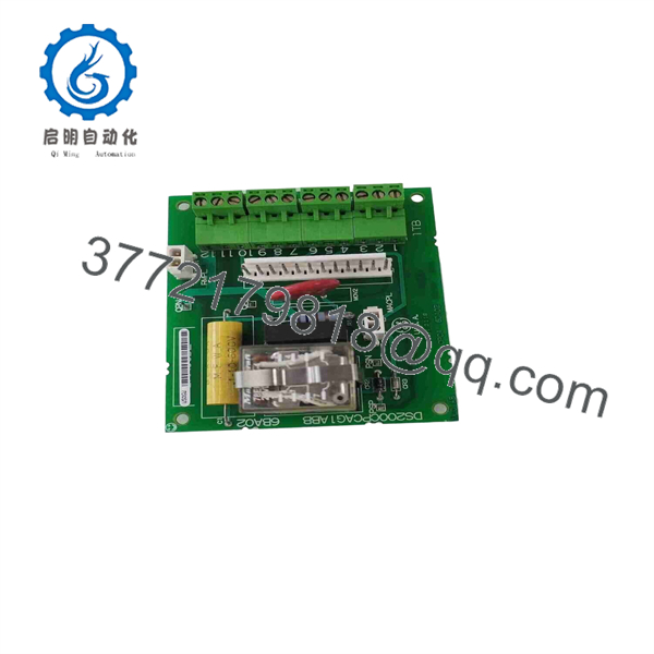
DS200CPCAG1ABB
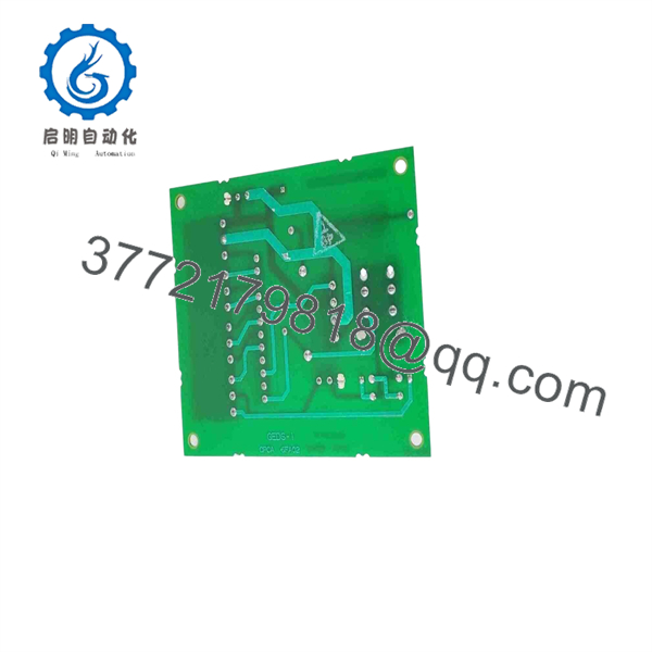
DS200CPCAG1ABB
Installation & Configuration Guide
Stage 1 — Pre-Installation Preparation
- Verify the complete PCB marking: DS200CPCAG1ABB.
- Record the existing board’s functional and artwork revision markings.
- Photograph all connector positions, terminal wiring, jumpers, and board-mounted configuration before removal.
- Back up the relevant Mark V control configuration and machine documentation.
- Follow the plant’s lockout/tagout procedure and isolate all associated AC and DC supplies.
- Treat the contactor circuitry as hazardous voltage equipment; do not rely solely on the controller being powered down.
- Prepare ESD protection, insulated hand tools, identification labels, and the correct replacement hardware.
Stage 2 — Removing the Old Module
- Verify absence of hazardous voltage with an appropriately rated meter.
- Allow the equipment to discharge according to the applicable GE/Mark V maintenance procedure.
- Label every terminal and connector before disconnecting it.
- Disconnect the 12-pin connector and the two 2-pin connectors by the connector body rather than pulling on conductors.
- Remove the wiring from the four terminal blocks while preserving the original terminal positions.
- Remove the board mounting hardware without flexing the PCB.
- Inspect the backplane, terminal wiring, relay socket, and connector contacts for heat damage, corrosion, or loose connections.
Stage 3 — Installing the New Module
- Confirm that the replacement is DS200CPCAG1ABB, not merely another DS200CPCAG1 variant.
- Compare the revision markings and physical connector arrangement with the removed board.
- Install the PCB in the original mounting position without excessive mechanical force.
- Reconnect the four terminal blocks exactly according to the recorded wiring.
- Reconnect the 12-pin and two 2-pin connectors and verify full seating.
- Confirm that no conductor is loose, pinched, or incorrectly landed.
- Check the associated contactor coils and external wiring for shorts before applying power.
- Do not substitute relay or contactor components solely from apparent electrical similarity; verify the applicable GE documentation and machine schematic first.
Stage 4 — Power-On & Testing
- Perform a final wiring, grounding, and insulation inspection.
- Confirm the correct AC/DC supply voltages before energizing the board.
- Energize the control system under the plant’s approved commissioning procedure.
- Check for abnormal relay operation, blown fuses, overheating, or unexpected contactor energization.
- Verify each associated contactor command individually at controlled conditions.
- Confirm that contactor feedback and associated Mark V logic respond correctly.
- Perform a controlled machine start/stop test before returning the turbine or driven equipment to normal operation.
- If a contactor does not operate correctly, isolate power and check the coil circuit, terminal wiring, relay operation, supply conversion circuit, and Mark V command path before replacing another board.
Frequently Asked Questions (FAQ)
Q1: What is the GE DS200CPCAG1ABB?
It is a Contactor Pilot Card for the GE Mark V turbine control system. It provides the interface and circuitry associated with contactor control rather than serving as a general-purpose communications processor.
Q2: Is DS200CPCAG1ABB a communications board?
No. The original functional description identifies it as a Contactor Pilot Card (CPCA). Some third-party listings incorrectly describe the part as a communications processor or controller, but those descriptions conflict with the documented Mark V function.
Q3: What are the main connectors on the board?
The board has one 12-pin connector and two 2-pin connectors, plus four terminal blocks capable of accepting up to 12 signal wires.
Q4: What contactor voltage is associated with the ?
The documented contactor circuitry uses 115 VDC coils. The board is described as converting incoming 115 VAC to approximately 105 VDC for applying the required voltage to close the contactors.
Q5: Can another DS200CPCAG1 board replace ?
Not automatically. The DS200CPCAG1 family contains multiple revisions and configurations. Verify the complete suffix, connector arrangement, revision markings, and machine wiring before accepting a substitute.
Q6: Is still a current GE production board?
It belongs to the legacy Mark V DS200 family and is no longer a current-generation control platform. Secondary-market suppliers continue to list new-surplus, refurbished, repair, and other conditions, so the actual condition of an individual unit must be confirmed with the supplier.
Q7: What should be checked before purchasing a replacement?
Confirm the complete part number, functional revisions A/B, artwork revision B, connector arrangement, board condition, and compatibility with the installed Mark V cabinet and wiring. A current 2026 supplier catalog lists four units of this exact part number, demonstrating that secondary-market inventory exists, but inventory and condition vary by supplier.



