
 WhatsApp: +86 16626708626
 Email:
  Phone: +86 16626708626
Description
3. Key Technical Specifications
| Parameter | Value |
|---|---|
| Functional Acronym | DCFB |
| Primary Function | DC Feedback / Control-Level Power Supply Board |
| Compatible Systems | Mark V; DC2000, AC2000, CB2000, ME2000, FC2000, EX2000 drives/exciters |
| Input Voltage | 38–115 VAC (from control power transformer) |
| Input Frequency | 0–500 kHz (voltage dependent) |
| Control Power Outputs | +5 V, ±15 V, ±24 V DC |
| Additional Output | 115 VAC for enclosure fans (typical) |
| Circuits Included | AC/DC monitoring, control-level supply, motor field power, SCR gate driver circuits |
| PCB Coating | Normal coating |
| Functional Revisions | B / L |
| Artwork Revision | C |
| Instruction Manual | GEI-100028 |
| Configuration | Jumpers and DIP switches (typical) |
| Weight (approx.) | 0.9–1 kg (2 lb) |
4. Product Introduction
The GE DS200DCFBG1BLC is a DC Feedback Power Supply Board (DCFB) used in the Mark V Speedtronic control system and associated GE drives and exciters (DC2000, AC2000, CB2000, ME2000, FC2000, and EX2000).
It receives 38–115 VAC from the control power transformer and generates the control-level DC supplies (+5 V, ±15 V, ±24 V) required by the drive electronics. It also provides power for enclosure cooling fans and includes motor/generator field power circuits (excluding the SCR module) plus driver circuits for the armature SCR gate pulse generators. AC and DC monitoring circuits allow instrumentation of armature current/voltage, field current, and AC line parameters.
This board carries the B/L functional revisions and C artwork revision. The Mark V platform is discontinued.
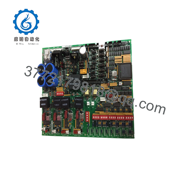
DS200DCFBG1BLC
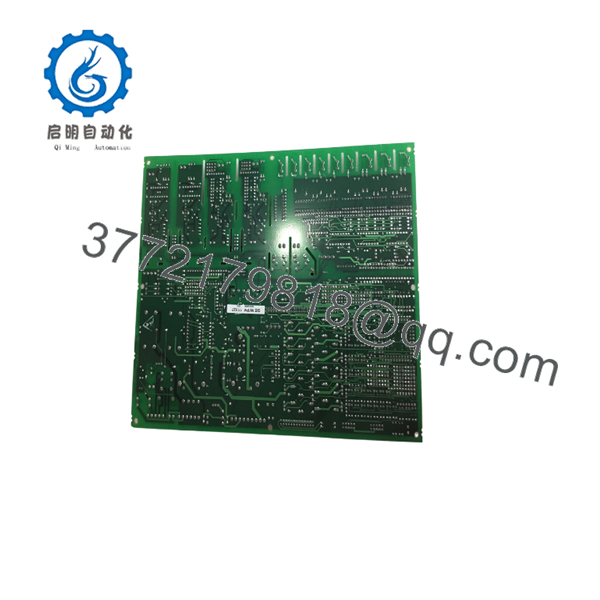
DS200DCFBG1BLC
5. Installation & Configuration Guide
Stage 1: Pre-Installation Preparation (15–20 min) ⚠️ Safety First: De-energize the entire drive/exciter cabinet. Wait several minutes for capacitors on the DS200DCFBG1BLC and related boards to discharge. Verify zero voltage with a meter before touching any circuits. Follow lockout/tagout. Tools Required: ESD wrist strap, multimeter, screwdriver set, GEI-100028 manual. Data Backup: Record existing jumper and DIP-switch settings from the old board. Note any drive-specific configuration.
Stage 2: Removing the Old Board (10–15 min)
- Confirm all power is removed and capacitors are discharged.
- Disconnect all cables and connectors attached to the DCFB board. Label every connection.
- Release the board from its mounting or card guides and carefully remove it. ⚠️ Avoid contact with residual charge on large capacitors.
Stage 3: Installing the New Board (15–25 min)
- Verify the board is marked DS200DCFBG1BLC and inspect for physical damage.
- Set jumpers and DIP switches to match the previous configuration or the drive manual requirements.
- Insert the board into the correct location and secure it.
- Reconnect all power, feedback, and control cables.
- Double-check grounding and connector seating. Self-Checklist: [ ] Jumpers/DIP switches correct [ ] All connectors fully seated [ ] No bent pins [ ] Power still off.
Stage 4: Power-On & Testing (20–40 min)
- Apply control power and observe board status indicators (LEDs/neon).
- Verify the presence of +5 V, ±15 V, and ±24 V at the appropriate test points.
- Confirm fan power and any field-circuit outputs if applicable.
- Run the drive/exciter through a controlled start sequence and monitor for faults related to power supplies or feedback signals.
- Check AC/DC monitoring signals for proper scaling. ⚠️ Troubleshooting Note: Missing control voltages usually indicate blown fuses, incorrect input AC, or a failed regulator section. Always re-verify capacitor discharge before any rework.
6. Frequently Asked Questions (FAQ)
Q: Can the DS200DCFBG1BLC be hot-swapped? No. Power must be completely removed and capacitors allowed to discharge before the board is removed or installed.
Q: Is the DS200DCFBG1BLC still in production? No. The Mark V series and associated DS200 boards are obsolete. Remaining units are new surplus or refurbished. Long-term strategy should include migration planning to Mark VIe or newer platforms.
Q: What drives/exciters is it compatible with? Primarily DC2000, AC2000, CB2000, ME2000, FC2000, and EX2000. Exact compatibility depends on the specific drive configuration and revision.
Q: What does the part number suffix mean? DS200 = Mark V series board, DCFB = DC Feedback / Power Supply function, G1 = group/revision base, BLC = specific functional and artwork revisions (B/L/C).
Q: Why is the price lower than historical OEM list price? These are genuine surplus units from excess inventory. They are original GE boards that have never been installed in a running system, but they are no longer available through standard GE channels. Functional testing and warranty are provided.
Q: Is there a manual for this board? Yes. The primary reference is GE instruction manual GEI-100028 (Power Supply Board).
Q: What power supplies does the board generate? Typical control-level outputs are +5 V, ±15 V, and ±24 V DC, derived from the 38–115 VAC input. It also supplies 115 VAC for enclosure fans in most applications.



