
 WhatsApp: +86 16626708626
 Email:
  Phone: +86 16626708626
Description
Key Technical Specifications
| Parameter | Value |
| Catalog / Part Number | DS200DCFBG1BNC |
| System Compatibility | GE Mark V Speedtronic Systems, DC2000 Drives, Innovation Series Drive Systems |
| Board Function | Direct Current Feedback (DCFB) Signal Conditioning |
| Revision Level | Group 1BNC (G1BNC – standard functional build revision) |
| Primary Inputs | AC/DC Voltage Attenuation, Motor Armature Voltage/Current, Field Current Feedback |
| Signal Processing | Isolation amplifiers, potential transformer (PT) signal attenuation, and current transformer (CT) conditioning |
| Board Connectors | Multiple multi-pin ribbon cable connectors (20-pin, 34-pin), high-voltage terminal posts, test points |
| Diagnostic Features | On-board LED indicators for power rails and gate pulse/drive run status |
| Operating Temperature | 0°C to +60°C (32°F to 140°F) |
Product Introduction & Supply Chain Strategy
The GE DS200DCFBG1BNC Direct Current Feedback Board (DCFB) is a crucial signal-conditioning module designed for General Electric’s legacy Mark V Speedtronic turbine controls, DC2000 drive cabinets, and Innovation Series power converters. The DCFB board sits between high-power motor/generator bridges and the sensitive digital control electronics. It safely scales down high armature voltages, monitors motor field currents, and provides isolated feedback loops to ensure safe motor torque and speed regulation.
Because GE has retired these legacy drive and control platforms, securing factory-sealed New Surplus DS200DCFBG1BNC boards is a vital risk-mitigation strategy for power plants, steel mills, and heavy industrial facilities. Utilizing new surplus inventory eliminates the severe operational hazards associated with second-hand or repaired drive boards, such as drifting precision attenuation resistors, degraded isolation optocouplers, or cracked high-voltage isolation barriers. Keeping a tested spare on-site enables rapid hot-standby swapping to prevent unscheduled mill or turbine trips.
Installation & Configuration Guide
Stage 1: Pre-Installation (Prep & Safety)
- Lock-Out/Tag-Out (LOTO): Isolate all 3-phase AC input power and 125V/250V DC bus power supplying the drive enclosure. Allow power supply filter capacitors to fully discharge (minimum 10–15 minutes) and verify zero voltage using a calibrated multimeter.
- Jumper Configuration Matching: Before installing the new board, inspect all hardware jumper blocks (e.g., JP1, JP2, etc.) on the existing DS200DCFB board and replicate their exact physical positions on the DS200DCFBG1BNC replacement.
- ESD Safety: Always wear a properly grounded anti-static wrist strap while handling the board to prevent static damage to sensitive onboard CMOS operational amplifiers and logic ICs.
Stage 2: Removal
- Carefully label all multi-pin ribbon cables, pluggable terminal blocks, and individual wire connections attached to the board.
- Unclip and disconnect the ribbon cables by pressing the retaining tabs outward.
- Remove the mounting screws holding the board onto the chassis standoffs, ensuring hardware does not drop into the lower power assembly.
Stage 3: Installation (Clone & Seat)
- Mount the new DS200DCFBG1BNC onto the chassis standoffs and tighten all retaining screws to secure grounding points.
- Reattach all ribbon cables and terminal wiring according to your labels, ensuring connectors snap into place securely.
- Visually verify that wire clearances meet high-voltage separation standards.
Stage 4: Power-On & Testing
- Re-apply control supply voltage to the drive while leaving the high-voltage armature line open.
- Check onboard diagnostic LEDs to confirm normal power rail (+5V, ±15V) initialization without board fault triggers.
- Re-energize main bus power, perform a zero-speed calibration/feedback check via the drive diagnostic terminal, and verify accurate voltage and current scaling readings.
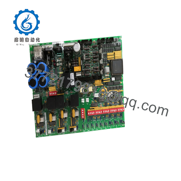
DS200DCFBG1BNC
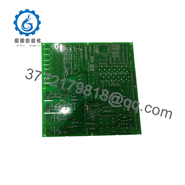
DS200DCFBG1BNC
Firmware/Software Versions & Upgrade Notes
- Hardware Hardware Revisions: The
G1BNCsuffix indicates the exact board layout, populated component options, and revision level. Replicating this exact revision code guarantees complete plug-and-play compatibility with existing control cabinet backplanes. - Calibration Parameters: Armature and field current scaling values are maintained within the main drive processor software. When replacing a DCFB board with an identical revision, recalibration is generally minimal, though verifying feedback feedback offsets using drive service tools is recommended.
Frequently Asked Questions (FAQ)
Is this GE DS200DCFBG1BNC unit guaranteed to be New Surplus and not refurbished?
Yes. This board is 100% Brand New Surplus stock in original OEM static-shielded packaging. It has never been installed in an active drive cabinet, energized in the field, or subjected to component-level circuit board repairs.
What is the core function of the DS200DCFB board in a GE drive system?
The Direct Current Feedback (DCFB) board attenuates high-voltage signals from the motor armature and field circuits down to low-voltage analog signals (+/- 10V / 0-5V) that can be safely processed by the digital drive control board for feedback monitoring and firing pulse generation.
Can I substitute a DS200DCFBG1A card for a card?
While both belong to the DS200DCFB family, the trailing revision code (G1BNC) signifies specific component revisions and circuit enhancements. It is always recommended to replace like-for-like (G1BNC with G1BNC) to avoid jumper configuration mismatches or signal level discrepancies.
Do I need to move socketed IC chips from my old board to the new ?
The is a fully populated board assembly. Unless specifically instructed by GE system service documentation for custom EPROM firmware configurations, no chip swapping is necessary. Simply mirror the hardware jumper configuration.
What warranty protection comes with this New Surplus board?
We support this GE New Surplus drive feedback board with a comprehensive 1-year replacement warranty. Every board undergoes strict visual inspection, anti-static verification, and ESD-safe packaging prior to shipment.



