
 WhatsApp: +86 16626708626
 Email:
  Phone: +86 16626708626
Description
3. Key Technical Specifications
| Parameter | Value |
|---|---|
| Manufacturer | General Electric |
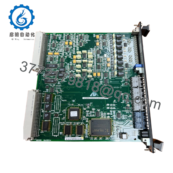
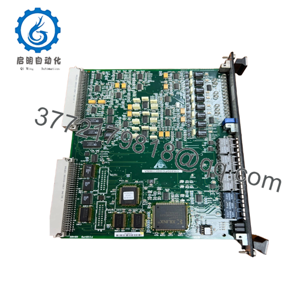
| Model Number | DS200FCGDH1BBA |
| Product Type | DSP Drive Control Module |
| Platform | GE Mark VI Drive Systems |
| Processor Type | Digital Signal Processor (DSP) |
| Communication Interface | VME Bus |
| Application | Industrial drive and exciter control |
| Bridge Type | Six-pulse phase-controlled non-reversing bridge |
| Input Supply | 24 V DC |
| Typical Power Consumption | Approximately 12 W |
| Operating Temperature | −40 °C to +70 °C |
| Cooling Method | Air-cooled system integration |
| Board Size | 8U format |
| Condition | New Surplus / Refurbished (tested) |
The DS200FCGDH1BBA is commonly identified as a GE DSP Drive Control module used in drive and exciter systems with VME communication architecture.
4. Product Introduction
GE DS200FCGDH1BBA is a DSP Drive Control Module used in GE industrial drive and excitation systems. The board executes drive control functions, SCR firing logic, diagnostics, and system-level signal processing for heavy industrial applications including turbine and high-power motor control systems.
In field deployments involving legacy GE drive systems, this board frequently appears in facilities where minimizing retrofit downtime matters more than redesigning an entire drive cabinet. The VME architecture and DSP processing structure allow direct replacement strategies if firmware and revision compatibility remain aligned.
5. Installation & Configuration Guide
Stage 1: Pre-Installation Preparation (Estimated: 10 minutes)
⚠️ Safety First: Notify operations personnel. Confirm controlled shutdown status. Apply lockout/tagout procedures. Remove cabinet power and wait at least 5 minutes for DC bus discharge.
Tools Required
- ESD wrist strap
- PH1 screwdriver
- Fluke 115 multimeter
- Wire labels
- Smartphone for photographs
- ESD work mat
Data Backup
- Export current drive parameters.
- Record cabinet slot locations.
- Photograph all wiring harnesses.
- Document board revision identifiers.
- Capture connector orientation and cable labels.
For legacy GE cabinets, photos save projects. Memory does not.
Stage 2: Removing the Old Module (Estimated: 8 minutes)
- Remove cabinet access cover.
- Label all harnesses before disconnecting.
- Disconnect ribbon cables carefully.
- Release retention hardware.
- Pull module straight out.
⚠️ Never twist the board during removal.
VME connector pins tolerate very little abuse.
Inspect:
- Bent pins
- Dust contamination
- Connector oxidation
- Loose hardware
⚠️ Keep the old board nearby until commissioning succeeds.
Stage 3: Installing the New Module (Estimated: 7 minutes)
- Wear ESD protection before handling electronics.
- Verify DS200FCGDH1BBA model and revision.
- Compare revision labels.
- Carefully insert board.
- Ensure full seating.
Configuration Clone (Crucial):
Replicate:
- DIP settings
- Jumper positions
- Address settings
- Bus termination settings
This is the most common rookie mistake, and experienced engineers still get caught by it.
Take a picture before pulling the old module.
Self-Checklist
[ ] Model verified
[ ] Revision verified
[ ] Wiring secure
[ ] Connectors seated
[ ] Lock tabs secured
Stage 4: Power-On & Testing (Estimated: 10 minutes)
Pre-Power Check
Use a multimeter:
- Verify no short across 24 V rail
- Check grounding continuity
- Verify harness seating
Power sequence:
- Power cabinet only.
- Observe LEDs.
- Green RUN = acceptable startup
- Red ERR = investigate fault
- Connect engineering workstation
- Verify firmware and communication status
- Perform dry-run I/O simulation
⚠️ Troubleshooting Note
Solid ERR LED after replacement usually points toward:
- firmware mismatch
- incorrect board revision
- VME communication issue
Do not immediately assume hardware failure.
Technical Pitfall & Survival Guide
❗ Firmware Revision Mismatch
This one has caused more overnight outages than people admit.
I’ve seen technicians replace a board and suddenly communication faults appear for two days.
Reason:
Old firmware V2.x replaced with V3.x hardware.
Document:
- existing firmware
- drive parameters
- board revisions
before shutdown.
❗ DIP Switch / Jumper Errors
Factory settings frequently do not match plant settings.
Take photographs.
I cannot stress this enough.
❗ Terminal Block / Wiring Differences
Even nearly identical GE board revisions can have connector differences.
Always compare:
- drawings
- shielding
- grounding
- pin assignments
Never wire from memory.
❗ Power Draw Problems
Drive cabinets often operate near supply limits.
Leave a minimum 20% capacity margin.
A slightly higher load can create nuisance faults that look like communication failures.
❗ ESD Damage
I watched a technician pull a board during winter shutdown work without a grounded strap.
Installed it.
Powered up.
Smoke immediately.
That board cost several thousand dollars.
Wear:
- ESD strap
- ESD mat
- anti-static gloves when available
Keep these checks in mind and you’ll save yourself 90% of typical rework time.
SOP Quality Transparency
1. Inbound Inspection & Traceability
- OEM packing verification
- Serial number logging
- Anti-counterfeit inspection
- Surface inspection
- UV discoloration check
- Accessory audit
2. Live Functional Testing
Test setup:
- Genuine GE drive simulation rack
Test sequence:
- Power-on self-test
- LED status verification
- VME communication validation
- I/O simulation
- 24-hour continuous operation
- Thermal monitoring
Official test report generated.
Photos and test videos available upon request.
3. Electrical Parameter Testing
- 500 V Megger insulation resistance >10 MΩ
- Ground continuity verification
- Hipot test where applicable
4. Firmware & Configuration Verification
- Firmware documented
- Revision photographed
- Configuration settings recorded
5. Final QC & Packaging
- QC inspector sign-off
- Anti-static ESD packaging
- Bubble protection
- Heavy-duty carton
- QC label with inspection date
Functionality verified under continuous load testing.
- DS200FCGDH1BBA
- DS200FCGDH1BBA
6. Frequently Asked Questions (FAQ)
Q1: Can I hot-swap DS200FCGDH1BBA?
No.
Do not attempt live replacement. VME architecture and industrial drive hardware do not tolerate hot insertion well. Backplane damage becomes expensive very quickly.
Q2: Is DS200FCGDH1BBA obsolete?
Yes.
This belongs to a legacy GE platform. Available inventory usually consists of New Surplus or tested refurbishment inventory. Stock availability changes frequently.
Q3: Is there a direct replacement?
Not always.
GE legacy systems often require matching board revisions and firmware levels. Verify OEM documentation before substituting another board.
Q4: Will replacing this board erase my logic?
Usually no.
This module primarily executes drive control functions. System logic and higher-level configuration generally remain elsewhere in the control architecture. Still, always back up parameters before maintenance.
Q5: Why are surplus prices lower than historical OEM pricing?
Because most inventory comes from plant shutdown stock, warehouse excess inventory, and surplus channels.
Request:
- serial verification
- actual photos
- test reports
- warranty documentation
before purchase.
Q6: Can refurbished units be used in production?
Depends on outage risk.
For emergency maintenance, tested refurbishment may be acceptable. For planned shutdowns in critical plants, I typically specify New Surplus stock.
Q7: What installation mistake causes the most rework?
Connector orientation.
At 2 AM during outage work, ribbon cables start looking identical.
Take photos before disconnecting anything. That one habit prevents a surprising number of mistakes.


