
 WhatsApp: +86 16626708626
 Email:
  Phone: +86 16626708626
Description
3. Key Technical Specifications
| Parameter | Value |
|---|---|
| Manufacturer | GE General Electric |
| Model | DS200FSAAG2ABA |
| Product Type | Field Supply Gate Amplifier Board |
| Series | Mark V Speedtronic |
| Functional Acronym | FSAA |
| Functional Revision | A/B/A |
| PCB Coating | Standard coating |
| Connectors | 1 × 10-pin, 4 × 2-pin |
| Jumper Configuration | 5–6 field-configurable jumpers |
| Fuse Protection | 2 × 30 A fast-acting fuses |
| Test Points | Multiple onboard diagnostic points |
| Application | Gas, steam, and turbine control systems |
| Mounting | Mark V rack installation |
| Approximate Dimensions | 11 × 4 in |
| Approximate Weight | 0.33–1.0 kg depending on packaging |
The Mark V platform and DS200FSAAG2ABA board design are part of GE’s legacy Speedtronic architecture and remain widely used in existing turbine installations.
4. Product Introduction
GE DS200FSAAG2ABA is a Mark V Field Supply Gate Amplifier Board used within GE Speedtronic turbine control systems. It manages field supply and amplification functions for gas and steam turbine applications where stable signal handling and controlled power delivery are required.
In field deployments of Mark V systems, these boards commonly stay in service long after OEM production stops. Engineers usually choose DS200FSAAG2ABA because it directly matches existing rack architecture and minimizes turbine downtime compared with redesigning around newer control platforms.
5. Installation & Configuration Guide
Stage 1: Pre-Installation Preparation (Estimated Time: 10 minutes)
⚠️ Safety First: Notify operations of downtime. Confirm process safe state. Apply lockout/tagout. Wait at least 5 minutes for discharge of stored energy.
Tools Required
- ESD wrist strap
- PH1 screwdriver
- Fluke 115 multimeter
- Wire labels
- Smartphone for photos
Data Backup
- Export turbine configuration files and logic backups.
- Record IP addresses and communication settings.
- Photograph every connector and jumper location.
- Capture terminal routing and wire colors.
Stage 2: Removing the Old Module (Estimated Time: 5 minutes)
- Remove cabinet cover or front access panel.
- Label all cable connections before removal.
- Disconnect cables carefully. Do not force connectors.
- Release retaining tabs.
- Pull board straight outward. Avoid side loading the backplane.
- Inspect rack pins for contamination or bent contacts.
⚠️ Keep the old module nearby until startup is complete. I have seen techs throw old hardware into scrap bins and then realize they forgot jumper settings.
Stage 3: Installing the New Module (Estimated Time: 10 minutes)
- Put on ESD protection.
- Verify DS200FSAAG2ABA exactly matches the removed part.
- Configuration Clone (Crucial): Copy every jumper position exactly.
- Check termination settings and addressing.
- Insert module evenly into the rack.
- Confirm seating pressure and locking engagement.
- Reattach cables.
Self-Checklist:
[ ] DIPs and jumpers match
[ ] Wiring secured
[ ] Lock tabs engaged
❗This is the most common rookie mistake, but it happens constantly. Take a picture before you pull it. I can’t stress this enough.
Stage 4: Power-On & Testing (Estimated Time: 5 minutes)
Pre-Power Check
Use a multimeter and verify no short exists on the supply rail.
Power-Up Sequence
- Energize rack power only.
- Observe startup LEDs.
- Verify communication status.
- Confirm software recognizes the board.
- Restore backup configuration if required.
- Perform dry-run I/O testing.
⚠️ Troubleshooting Note: Solid fault indication immediately after installation often points to configuration mismatch or revision differences.
Veteran Survival Guide — Replacement Pitfalls
❗Firmware Revision Mismatch
I have seen a turbine outage drag into a second shift because a replacement board revision behaved differently than the original installation. Document the existing revision before removal. Request specific revision ranges if possible.
❗DIP Switch / Jumper Misconfiguration
This happens constantly. Somebody pulls a board, forgets the settings, installs the new one, and spends hours tracing “mystery faults.” Take photos before touching anything.
❗Terminal and Connector Assumptions
Even similar GE Mark V hardware revisions can introduce connector changes. Verify against documentation. Do not wire from memory.
❗Power Budget Oversight
Calculate rack loading and leave at least a 20% margin. I have watched power supplies operate fine for years until one additional module pushed them over the edge.
❗ESD Damage
I once watched an engineer replace a board during winter with no wrist strap. Powered it up and immediately released smoke. Expensive lesson.
Keep these checks in mind and you’ll save yourself 90% of typical rework time.
SOP Quality Transparency
1. Inbound Inspection & Traceability
- Verify OEM packaging records and supply chain documentation
- Check serial numbers and anti-counterfeit labels
- Inspect PCB for corrosion, scratches, UV yellowing, or rework evidence
- Audit included accessories and certificates
2. Live Functional Testing
Testing performed on a genuine GE Mark V test environment where available.
Procedure:
- Power-on verification
- LED and startup sequence checks
- Connector continuity verification
- Communication checks
- I/O simulation
- Continuous thermal operation for more than 24 hours
- Generate documented test report
Test photos and videos available upon request.
3. Electrical Parameter Testing
- Insulation resistance test using 500 V Megger (>10 MΩ target)
- Ground continuity check
- Voltage verification using Fluke 115 meter
- Hipot test when applicable
4. Firmware & Configuration Verification
- Document board revision details
- Photograph jumper positions
- Record hardware identifiers
5. Final QC & Packaging
- QC signoff
- Anti-static ESD packaging
- Bubble wrap protection
- Heavy-duty corrugated shipping box
- QC label with inspection date
Verified fully functional under load testing.
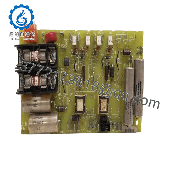
- DS200FSAAG2ABA
6. Frequently Asked Questions (FAQ)
Q1: Can I hot-swap this module?
No. Do not attempt it.
Mark V hardware was not designed around modern hot-swap practices. Pulling a board under power can damage the rack or create backplane faults. Kill power first.
Q2: Is DS200FSAAG2ABA obsolete, and is it genuinely new?
Yes. This is an obsolete GE Mark V component. OEM production stopped years ago. Most inventory today falls into New Surplus or tested refurbished stock categories.
Q3: What is the replacement if stock becomes unavailable?
Replacement depends on turbine configuration and board revision history. Some sites migrate toward newer GE control architectures, but direct substitutions should always be verified against OEM documentation.
Q4: Will I lose programming when removing this board?
Normally no. This board is not the primary logic processor. Still, always back up the running configuration first. I learned long ago not to trust assumptions during outages.
Q5: Why is pricing lower than OEM list pricing?
Most inventory comes from surplus channels, plant decommissioning projects, or excess procurement stock rather than current OEM manufacturing. That changes pricing structure.
Q6: Is New Surplus different from Refurbished?
Yes.
New Surplus generally means unused inventory stored after procurement or project cancellation. Refurbished hardware has been cleaned, tested, and verified functional after prior use.
Q7: Are test reports available before shipment?
Yes. We recommend requesting startup photos, communication checks, and load-test records before purchase. Test documentation helps avoid surprises during installation.


