
 WhatsApp: +86 16626708626
 Email:
  Phone: +86 16626708626
Description
3. Key Technical Specifications
| Parameter | Value |
|---|---|
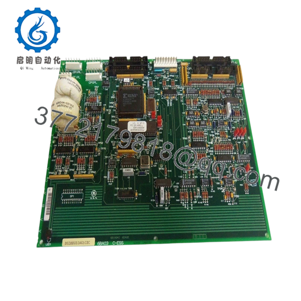
| Model Number | DS200GSIAG1CEC |
| Manufacturer | GE General Electric |
| Product Type | Common DC Bus Regenerative Board |
| Product Series | GE Mark V Speedtronic DS200 |
| Functional Acronym | GSIA |
| Application | Turbine and industrial drive systems |
| Connector Count | Three 40-pin, two 16-pin, one 8-pin |
| Jumper Count | Six configurable jumpers |
| Test Points | Multiple onboard test points |
| PCB Coating | Standard coating |
| Weight | Less than 5 lb |
| Operating Environment | Verify OEM installation requirements |
| Installation Type | Control cabinet board rack |
| Product Status | Legacy / Discontinued |
The DS200GSIAG1CEC functions as a Common DC Bus Regenerative Board within GE Mark V systems and includes multiple connector interfaces and configurable jumpers used for integration and control. Available documentation for this exact revision is limited because of product age and discontinuation status.
4. Product Introduction
The GE DS200GSIAG1CEC is a Common DC Bus Regenerative Board used within GE Mark V Speedtronic turbine and industrial drive control systems. It manages regenerative energy functions and supports control communication inside legacy GE architectures.
In field deployments of older Mark V cabinets, GSIA boards frequently remain in service for decades. Plants usually keep spare inventory because OEM manufacturing ended years ago and obtaining a matching revision during an outage can become difficult. Availability varies significantly by revision suffix and condition.
- DS200GSIAG1CEC
5. Installation & Configuration Guide
Stage 1: Pre-Installation Preparation (Estimated Time: 10 minutes)
⚠️ Safety First: Notify operations of downtime. Verify process safe state. Apply lock out/tag out. Wait at least 5 minutes for bus capacitor discharge.
Tools Required
- ESD wrist strap
- PH1 screwdriver
- Fluke 115 multimeter
- Wire labels
- Smartphone for photos
- Flashlight
Data Backup
- Export controller and drive parameters if accessible.
- Record fault history.
- Photograph all cable positions.
- Document board revision labels.
- Photograph jumper settings.
⚠️ GE Mark V systems often contain field modifications from previous outages. Cabinet drawings may not match actual wiring.
Stage 2: Removing the Old Module (Estimated Time: 5–10 minutes)
Steps:
- Remove cabinet panels.
- Label each connector.
- Disconnect wiring carefully.
- Release retaining hardware.
- Pull board straight out.
Inspect:
- Connector pins
- Dust accumulation
- Backplane condition
- Corrosion marks
⚠️ Keep the removed board nearby during startup.
I have seen technicians discover an undocumented jumper three hours into troubleshooting because the original board had already disappeared into a spare parts cabinet.
Stage 3: Installing the New Module (Estimated Time: 5 minutes)
Steps:
- Attach grounded ESD strap.
- Verify exact model: DS200GSIAG1CEC
- Configuration Clone (Crucial): Match all jumper settings exactly.
- Insert board evenly into rack guides.
- Confirm full seating.
- Reconnect cables.
Self-Checklist:
- DIPs match
- Jumpers verified
- Wiring secured
- Retainers locked
❗This is the most common rookie mistake, but experienced technicians get caught too. Take a photo before removal. I can’t stress this enough.
Stage 4: Power-On & Testing (Estimated Time: 10 minutes)
Pre-Power Check
Use a multimeter and verify no short exists on the 24 V rail.
Power sequence:
- Energize rack only.
- Observe startup indicators.
- Connect engineering workstation.
- Verify communication status.
- Restore backup settings if required.
- Run dry I/O testing.
LED interpretation:
- Green RUN: Normal state
- Red ERR: Fault state
⚠️ Troubleshooting Note: Immediate faults after replacement frequently indicate revision mismatch or configuration differences.
I’ve seen a replacement project consume two full shifts because firmware moved between revisions and communication timing changed enough to create intermittent faults. The hardware looked identical.
6. Frequently Asked Questions (FAQ)
Q1. Can I hot-swap this module?
No.
Do not insert or remove this board under power. Mark V hardware was not designed for live replacement. Hot-swapping can damage backplane circuitry and create faults that are difficult to isolate.
Q2. Is DS200GSIAG1CEC obsolete?
Yes.
This is a discontinued GE legacy component. New inventory usually comes from surplus channels or warehouse stock. Refurbished tested units are also common.
Q3. Is a DS200GSIAG1CFD or DS200GSIAG1CGD interchangeable?
Do not assume interchangeability.
GE revision suffixes matter. Hardware revisions can change functionality, connector behavior, or communication timing. Review:
- Revision suffixes
- Jumper arrangements
- Firmware compatibility
- OEM cross-reference notes
I’ve seen projects lose two days chasing a “communication timeout” fault caused by a revision jump.
Q4. Will I lose programming logic during replacement?
Typically no.
The DS200GSIAG1CEC acts as a functional board inside the Mark V architecture. Application logic generally resides elsewhere. Even so, always create backups before touching legacy systems.
Trusting assumptions during outages gets expensive.
Q5. Why is your price lower than historical OEM pricing?
Because GE stopped manufacturing these boards years ago.
Current pricing depends on:
- New surplus availability
- Repair history
- Revision level
- Test documentation
- Warranty period
Two identical part numbers may have very different field histories.
Q6. How are boards tested before shipment?
Our standard QC process follows this order:
Inbound Inspection & Traceability
- Source verification
- Label and serial review
- Anti-counterfeit checks
- Visual inspection for corrosion and repair marks
Live Functional Testing
- Compatible GE rack testing where available
- Power-up verification
- Communication checks
- Simulated I/O testing
- Continuous load operation over 24 hours
Electrical Testing
- 500 V insulation resistance test (>10 MΩ)
- Ground continuity check
- Hipot testing if applicable
Firmware & Configuration Verification
- Revision recording
- Jumper documentation
Final QC
- Inspector sign-off
- ESD packaging
- Bubble protection
- Heavy-duty shipping box
Test photos and videos are available upon request.
Q7. What installation mistake causes the most downtime?
❗Jumper and configuration mismatch.
I’ve watched engineers replace a board in fifteen minutes and spend six hours troubleshooting because one jumper stayed at factory default.
Keep these checks in mind and you’ll save yourself 90% of typical rework time.


