
 WhatsApp: +86 16626708626
 Email:
  Phone: +86 16626708626
Description
3. Key Technical Specifications
| Parameter | Value |
|---|---|
| Manufacturer | General Electric |
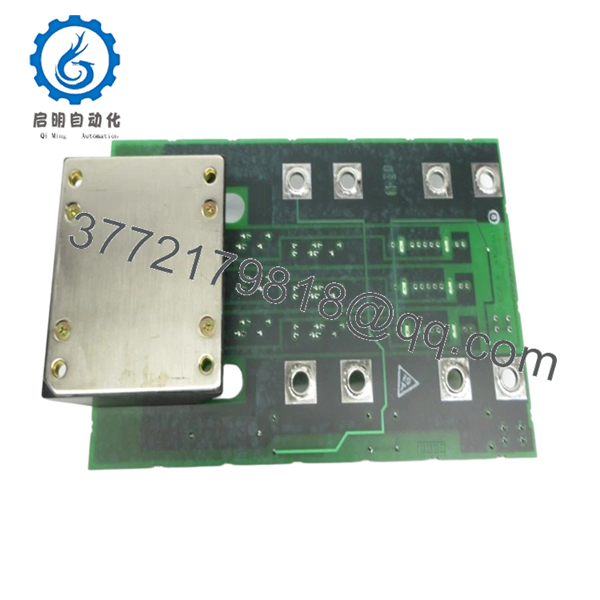
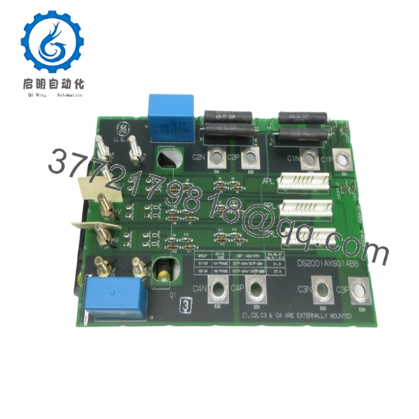
| Model Number | DS200IAXSG1ABB |
| Functional Description | IGBT AA/AB Snubber Card |
| Product Family | GE Speedtronic Mark V DS200 |
| Functional Abbreviation | IAXS |
| Product Revisions | Functional Rev A + Functional Rev B + Artwork Rev B |
| Interface Type | Multi-input / multi-output PCB |
| Connector Quantity | 3 × 8-pin connectors |
| Board Assembly | Standard DS200 assembly |
| Hardware Features | Voltage limiting capacitors and diodes |
| Weight | Approximately 5 lb |
| PCB Coating | Standard protective coating |
| Application | Turbine and drive control systems |
| Condition | New Surplus / Refurbished (tested) |
The DS200IAXSG1ABB is a GE Mark V IGBT AA/AB Snubber Card used within the Speedtronic control family and incorporates three hardware revisions in its assembly.
4. Product Introduction
GE DS200IAXSG1ABB is an IGBT AA/AB Snubber Card used within GE Speedtronic Mark V control systems. The board functions as a voltage suppression and transient protection interface associated with IGBT circuitry and drive electronics used in turbine and industrial control applications.
In field deployments involving legacy Mark V cabinets, this board commonly appears in systems where replacing the complete drive architecture is not practical. The snubber circuitry protects switching components from voltage spikes and helps prevent IGBT stress conditions during operation.
- DS200IAXSG1ABB
- DS200IAXSG1ABB
5. Installation & Configuration Guide
Stage 1: Pre-Installation Preparation (Estimated: 10 minutes)
⚠️ Safety First: Notify operations of downtime. Verify process safe-state conditions. Apply lockout/tagout procedures and remove control power. Wait at least 5 minutes for capacitor discharge.
Drive cabinets and turbine systems can retain stored energy after shutdown. Never trust panel indicators alone.
Tools Required
- ESD wrist strap
- PH1 screwdriver
- Fluke 115 multimeter
- Wire labels
- Smartphone for photographs
- ESD-safe work mat
Data Backup
- Export controller and drive parameters.
- Photograph connector positions.
- Record board slot location.
- Photograph wiring harnesses.
- Record cabinet labeling and board revisions.
Stage 2: Removing the Old Module (Estimated: 8 minutes)
- Remove cabinet cover.
- Label all connectors.
- Disconnect wiring and ribbon cables carefully.
- Release retaining hardware.
- Pull board straight outward.
⚠️ Do not twist the board.
I have seen technicians flex these boards trying to speed up removal. Bent connectors become tomorrow’s outage.
Inspect:
- Connector pins
- Dust contamination
- Oxidation
- Loose hardware
⚠️ Keep the old board nearby until startup verification succeeds.
Stage 3: Installing the New Module (Estimated: 7 minutes)
- Connect ESD protection first.
- Verify exact part number: DS200IAXSG1ABB
- Verify revision identifiers.
- Install board carefully into slot.
- Confirm connector engagement.
Configuration Clone (Crucial):
This board family can involve connector-specific placement and board orientation dependencies.
Verify:
- Connector locations
- Harness orientation
- Mechanical placement
- Grounding hardware
Take photos before removal.
This is the most common rookie mistake. Experienced people still make it during outage work.
Self-Checklist
[ ] Model verified
[ ] Revision verified
[ ] Connectors secure
[ ] Mounting hardware tightened
[ ] Tabs locked
Stage 4: Power-On & Testing (Estimated: 10 minutes)
Pre-Power Check
Using a Fluke 115:
- Verify no short across control supply rails
- Verify cabinet ground continuity
- Verify connector seating
Power-on sequence:
- Power control cabinet only.
- Observe startup status.
- Monitor alarms.
- Verify communication status.
- Perform dry-run simulation.
- Check voltage behavior during operation.
⚠️ Troubleshooting Note: If faults appear immediately after startup, verify connector placement before assuming board failure. I have watched maintenance teams replace perfectly good boards because one connector shifted one position.
Technical Pitfall & Survival Guide
❗ Firmware Revision Mismatch
Legacy GE systems can be extremely revision-sensitive.
I’ve seen technicians replace hardware and suddenly lose communication across connected systems for two days. Firmware moved from one revision family to another and diagnostics looked unrelated.
Avoidance:
- Record firmware versions
- Record board revisions
- Request matching revision ranges
❗ DIP Switch / Jumper Misconfiguration
This mistake happens constantly.
Take a picture before you pull it.
I cannot stress this enough.
Factory defaults are not plant settings.
❗ Terminal Block / Wiring Incompatibility
Even similar DS200 variants can contain connector differences.
Always verify:
- wiring diagrams
- shielding methods
- pinouts
- grounding
Never wire from memory.
❗ Power Draw Specifications
Always calculate cabinet loading.
Leave a minimum 20% margin.
One overloaded supply creates nuisance alarms that waste hours.
❗ Electrostatic Discharge (ESD)
I watched an engineer grab a replacement board during winter shutdown work with no grounded strap.
Installed it.
Powered it.
Smoke immediately.
Several thousand dollars disappeared in less than ten seconds.
Use:
- Grounded ESD strap
- ESD work mat
- Anti-static packaging
Keep these checks in mind and you’ll save yourself 90% of typical rework time.
SOP Quality Transparency
1. Inbound Inspection & Traceability
- OEM packing verification
- Serial number documentation
- Anti-counterfeit checks
- Surface inspection
- Corrosion inspection
- UV discoloration inspection
- Accessory verification
2. Live Functional Testing
Testing environment:
- Genuine GE Mark V rack simulation platform
Procedure:
- Power-on self-test
- LED monitoring
- Communication verification
- Simulated load testing
- Continuous operation exceeding 24 hours
- Thermal monitoring
Official test reports generated.
Photos and startup videos available upon request.
3. Electrical Parameter Testing
- 500 V Megger insulation resistance >10 MΩ
- Ground continuity test
- Hipot test where applicable
4. Firmware & Configuration Verification
- Firmware recorded
- Board revisions photographed
- Configuration documented
5. Final QC & Packaging
- QC sign-off
- Anti-static ESD packaging
- Bubble wrap protection
- Heavy-duty corrugated packaging
- QC Passed labeling with date
Board functionality verified under sustained load conditions.
6. Frequently Asked Questions (FAQ)
Q1: Can I hot-swap DS200IAXSG1ABB?
No.
Do not attempt live replacement. Snubber boards interface with high-energy circuitry. Hot-swapping can damage associated IGBT hardware and backplane circuitry.
Q2: Is DS200IAXSG1ABB obsolete?
Yes.
This is discontinued GE Mark V hardware. Most available inventory comes from New Surplus stock or tested refurbishment channels. Availability changes frequently.
Q3: Is there a direct replacement?
Not automatically.
GE board revisions matter. DS200IAXSG1ABB differs from earlier revisions and compatibility must be checked before substitution.
Q4: Why are there multiple revision letters?
GE revision identifiers are not decoration.
A/B revision changes may affect board behavior, component layout, or compatibility. Verify before ordering.
I’ve seen maintenance teams ignore one suffix and create an outage window that doubled in length.
Q5: Will I lose control logic when replacing this board?
No.
This board is not the controller CPU. It serves hardware-level IGBT snubber functions. Control logic typically remains elsewhere in the system architecture.
Q6: Why are New Surplus units cheaper than historical OEM pricing?
Because most inventory originates from plant shutdown stock, excess warehouse inventory, and discontinued inventory channels.
Request:
- actual photos
- serial verification
- test reports
- warranty documents
before purchasing.
Q7: What causes the most replacement mistakes?
Connector placement.
At 2 AM, during outage work, every connector starts looking identical.
Photos prevent arguments later.


