
 WhatsApp: +86 16626708626
 Email:
  Phone: +86 16626708626
Description
3. Key Technical Specifications
| Parameter | Value |
|---|---|
| Manufacturer | General Electric |
| Model | DS200PCCAG6ACB |
| Product Acronym | PCCA |
| Product Type | Power Connect Card Assembly |
| Series | GE Mark V Speedtronic |
| Manual Reference | GEI-100161 |
| Functional Role | Interface to SCR power bridge |
| Connector Count | 12 SCR interface connectors + 1 power interface |
| Group Type | G6 |
| Regenerative Voltage Range | 240–630 V |
| Non-Regenerative Voltage Range | 240–700 V |
| Frame Compatibility | J, K, M |
| PCB Coating | Normal coating |
| Revision Structure | Functional A/C, Artwork B |
| Typical Applications | EX2000, DC2000, turbine control drives |
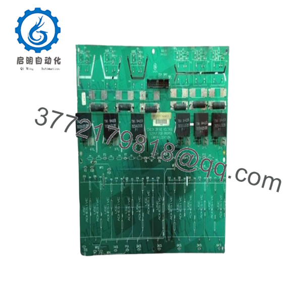
The DS200PCCAG6ACB acts as the interface between the drive control section and SCR power bridge hardware. It supports gate pulse transmission and drive configuration functions in GE Mark V systems.
4. Product Introduction
GE DS200PCCAG6ACB is a Power Connect Card Assembly used in GE Mark V Speedtronic turbine and drive systems. The board interfaces with SCR power bridges and supports gate pulse transmission, voltage range selection, and drive configuration functions.
In field deployments of GE EX2000 and DC2000 systems, boards like this frequently stay in service for decades. Plants typically replace the board itself rather than redesigning an entire excitation or turbine control architecture. That decision usually comes down to downtime risk and engineering cost.

- DS200PCCAG6ACB
5. Installation & Configuration Guide
Stage 1: Pre-Installation Preparation (Estimated: 10 minutes)
⚠️ Safety First: Notify operations of planned downtime. Confirm process shutdown status. Lock out and tag out cabinet power. Wait 5 minutes minimum for stored energy discharge.
Tools Required
- ESD wrist strap
- PH1 screwdriver
- Fluke 115 multimeter
- Wire labels
- Smartphone for documentation
- Flashlight
Data Backup
- Export drive configuration files.
- Record cabinet location and slot number.
- Photograph every connector before removal.
- Record jumper positions and labels.
- Document software parameters and regulator settings.
I have seen technicians rely on memory because “there are only a few plugs.” Thirty minutes later they are tracing twelve identical connectors across a crowded cabinet.
Stage 2: Removing the Old Module (Estimated: 5–10 minutes)
- Remove cabinet panels.
- Label every connector before removal.
- Disconnect wiring carefully.
- Release mounting hardware.
- Pull board straight out.
⚠️ Never rock the board side-to-side.
Mark V backplane connectors are not forgiving. Bent pins can create intermittent faults that appear only under load.
Inspect:
- Bent pins
- Dust accumulation
- Heat damage
- Connector discoloration
- Oxidation
⚠️ Keep the removed module available until startup verification completes.
Stage 3: Installing the New Module (Estimated: 10 minutes)
- Wear ESD protection.
- Verify DS200PCCAG6ACB matches exactly.
- Configuration Clone (Crucial): Replicate all jumpers and configuration hardware.
- Insert evenly.
- Verify complete seating.
- Reconnect field wiring.
Self-check:
- Configuration copied
- Wiring secured
- Connectors fully seated
- Mounting hardware locked
❗Take photos before pulling the original hardware.
This sounds basic, but I still see experienced technicians skip it.
Stage 4: Power-On & Testing (Estimated: 10–15 minutes)
Pre-Power Check
Use a multimeter to verify no shorts on control power rails.
Power sequence:
- Energize rack power only.
- Observe startup indicators.
- Verify communication.
- Connect engineering software.
- Verify drive parameters.
- Perform dry-run signal checks.
⚠️ Troubleshooting Note:
If the replacement board initializes but communication faults appear, investigate revision differences before replacing additional components.
I’ve watched maintenance teams spend two days replacing perfectly good hardware because nobody checked board revision history.
Quality Verification SOP
Incoming inventory inspection sequence:
1. Inbound Inspection & Traceability
- OEM packing verification
- Serial checks
- Anti-counterfeit verification
- Visual inspection for scratches, corrosion, UV yellowing, and rework marks
- Accessory audit
2. Live Functional Testing
Test environment:
- Genuine GE Mark V test rack where available
Procedure:
- Power-on self-test
- LED verification
- Signal handshake testing
- I/O simulation
- Continuous operation exceeding 24 hours with thermal monitoring
Official test reports generated.
3. Electrical Testing
- 500 V Megger insulation testing (>10 MΩ target)
- Ground continuity checks
- Hipot testing where design permits
4. Firmware & Configuration Verification
- Revision documentation
- Jumper photography
- Configuration recording
5. Final QC and Packaging
- QC sign-off
- ESD anti-static packaging
- Bubble protection
- Heavy-duty carton packaging
- QC inspection labeling
Test photos and videos available upon request.
Technical Pitfall & Survival Guide
❗ Firmware Revision Mismatch
Document original revisions before removal.
I saw a drive replacement generate communication timeout alarms for nearly two days. Turned out firmware changed between revisions.
The hardware looked identical.
❗ DIP Switch / Jumper Errors
This is still the most common installation mistake.
Take photos before removal.
Do not trust memory.
❗ Connector Assignment Assumptions
Even similar GE boards can move connector functions between revisions.
Always verify wiring drawings.
Do not wire from memory.
❗ Power Consumption Planning
Leave at least 20% spare power capacity.
Adding additional drive modules can quietly push cabinet supplies beyond acceptable limits.
❗ ESD Damage
I watched an engineer handling a board during winter without an ESD strap.
Powered it up.
Instant smoke.
Several thousand dollars disappeared in one second.
Keep these checks in mind and you’ll save yourself 90% of typical rework time.
6. Frequently Asked Questions (FAQ)
Q1: Can I hot-swap this module?
No.
Mark V systems were not designed for live insertion of PCCA hardware. Pulling the board under power can damage SCR interfaces or backplane connections.
Power down first.
Q2: Is DS200PCCAG6ACB obsolete?
Yes.
This is a legacy GE Mark V product. Most inventory now comes from surplus stock or tested refurbished inventory rather than active production.
Q3: Is inventory genuinely new?
Sometimes.
“New Original” often means unused surplus inventory stored for years. Packaging conditions vary because these products have been out of active manufacturing for a long time.
Request photos before purchase.
Q4: What systems use this board?
Typical installations include:
- GE Mark V
- EX2000
- DC2000
- SCR bridge systems
The board interfaces directly with SCR bridge hardware and drive controls.
Q5: Will I lose programming during replacement?
Normally no.
The PCCA board does not function as the main logic processor. Application logic typically resides elsewhere in the system.
Still create backups first.
Q6: Why are surplus prices lower than OEM pricing?
Most stock comes from surplus inventories, plant closures, or spare-part programs.
You are paying for inventory availability rather than current factory production.
Q7: What warranty is typical?
Most tested inventory carries a 12-month warranty, although terms vary by supplier and stock condition.


