
 WhatsApp: +86 16626708626
 Email:
  Phone: +86 16626708626
Description
3. Key Technical Specifications
| Parameter | Value |
|---|---|
| Manufacturer | GE General Electric |
| Model Number | DS200PCCAG9ACB |
| Product Type | Power Connect Card Assembly |
| Functional Acronym | PCCA |
| Series | Mark V DS200 |
| Revision | ACB |
| Scaling Group | G9 Regenerative |
| Supported Armature Voltage | 240–630 V |
| AC Input Capability | ≤ 600 V RMS |
| Compatible Drive Frames | J and M Frames |
| Snubber Configuration | DC Snubbers Only |
| Bus Transformer Support | Separate or Common Bus |
| PCB Coating | Standard Industrial Coating |
| Connector Configuration | Multi-point stab and ribbon interfaces |
| Instruction Manual | GEI-100161 |
| Approximate Weight | 9 oz (255 g) |
| Country of Origin | United States |
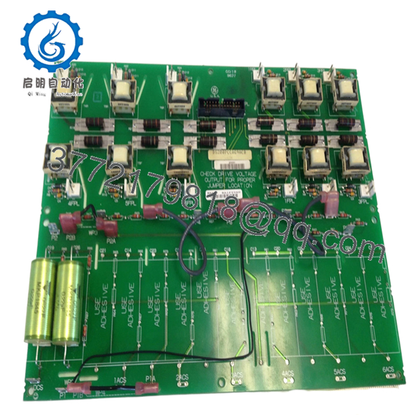
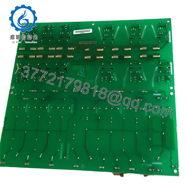
The DS200PCCAG9ACB functions as the interface between the SCR bridge and the drive control section inside GE Mark V regenerative drive systems. Verify compatibility against the installed drive frame and scaling group before installation.
4. Product Introduction
The GE DS200PCCAG9ACB is a Power Connect Card Assembly used in GE Mark V turbine and regenerative drive systems. It manages power distribution and control signal interfacing between the SCR power bridge and the drive control electronics.
In field service environments, this board is commonly found in older GE regenerative drive cabinets operating on J and M frame configurations. Plants continue using this model because replacing the entire Mark V drive architecture usually costs substantially more than maintaining qualified spare inventory.

- DS200PCCAG9ACB
- DS200PCCAG9ACB
5. Installation & Configuration Guide
Stage 1: Pre-Installation Preparation (Estimated Time: 10–15 Minutes)
⚠️ Safety First
- Notify operations before shutdown.
- Place the drive and associated process in a verified safe state.
- Lock out/tag out all incoming power sources.
- Wait at least 5 minutes for DC bus capacitors to discharge.
- Verify zero energy using a multimeter before touching terminals.
This board interfaces directly with regenerative power circuitry. Residual DC bus voltage can remain present longer than expected.
Tools Required
- Grounded ESD wrist strap
- PH1 and PH2 screwdrivers
- Fluke 115 multimeter or equivalent
- Insulated gloves
- Wire labels
- Smartphone for documentation photos
- Flashlight for cabinet inspection
Data Backup
- Export drive parameters and backup controller configuration.
- Record cabinet slot location.
- Photograph:
- Jumper locations
- Connector orientation
- Cable routing
- Ground straps
- Label every disconnected cable.
⚠️ I’ve seen experienced techs assume they would “remember the wiring.” Six hours later they’re tracing ribbon cables one conductor at a time.
Stage 2: Removing the Old Module (Estimated Time: 10 Minutes)
- Remove the cabinet access cover.
- Label and disconnect all connectors carefully.
- Disconnect stab connectors without twisting.
- Remove retaining screws.
- Pull the board straight outward to protect edge connectors.
- Inspect:
- Connector oxidation
- Burn marks
- Cracked solder joints
- Dust contamination
- Heat stress around snubber sections
⚠️ Important: Keep the original board nearby until the replacement passes operational testing.
A replacement board can physically fit while still being electrically incompatible because of group revision differences.
Stage 3: Installing the New Module (Estimated Time: 10 Minutes)
- Wear the grounded ESD strap before handling the PCB.
- Verify exact model:
- DS200PCCAG9ACB
- Confirm:
- G9 scaling group
- ACB revision
- J/M frame compatibility
Configuration Clone (Crucial)
Replicate all hardware configuration exactly:
- JP1 jumper settings
- JP2 jumper settings
- WP3 and WP4 wire jumpers
- Bus transformer configuration
- Termination wiring
⚠️ This is the most common startup failure point. One incorrect jumper can prevent the regenerative bridge from initializing properly.
- Install the board evenly into the mounting rails.
- Tighten mounting hardware evenly.
- Reconnect all power and signal connectors.
Self-Checklist
- Model number matches
- Scaling group verified
- Jumpers copied exactly
- Connectors fully seated
- Grounding secured
- No loose hardware in cabinet
Stage 4: Power-On & Testing (Estimated Time: 15–20 Minutes)
Pre-Power Check
- Verify no short exists across the DC rail.
- Confirm cabinet grounding continuity.
- Inspect for loose stab connections.
Power-On Sequence
- Energize the control rack first.
- Observe board indicators and drive diagnostics.
- Verify communication with the Mark V controller.
- Confirm regenerative bridge initialization.
- Monitor DC bus stability.
- Perform dry-run testing before enabling field loads.
Communication & Functional Testing
- Verify proper SCR bridge communication.
- Confirm no gate firing faults.
- Check for:
- Overvoltage alarms
- Bus mismatch faults
- Regeneration errors
- Drive handshake failures
⚠️ Troubleshooting Note
If the drive faults immediately during startup:
- First check jumper configuration.
- Second verify scaling group compatibility.
- Third inspect bus transformer wiring.
I once saw a replacement PCCA board installed into the wrong frame type during an outage. The board powered correctly, but regenerative control behaved erratically under load. Took nearly an entire shift to trace the issue back to frame incompatibility.
Technical Pitfall & Survival Guide
❗ Firmware and Revision Mismatch
Not all DS200 revisions behave identically.
Avoidance:
Document both firmware revision and board suffix before ordering.
I’ve seen Mark V systems reject newer revision hardware because timing behavior shifted slightly between revisions.
❗ Jumper Misconfiguration
Incorrect jumper settings can disable bridge synchronization.
Avoidance:
Photograph every jumper before removal. Mirror the configuration exactly.
Do not trust factory defaults.
❗ Frame Compatibility Errors
This board is intended for J and M frame systems only.
Avoidance:
Verify frame type before installation.
A board may physically mount while still operating incorrectly electrically.
❗ Power Supply Loading
Regenerative systems generate significant transient loading.
Avoidance:
Verify power supply margins and DC bus stability before startup.
Leave at least 20% current overhead on cabinet supplies.
❗ Electrostatic Discharge (ESD)
These boards are highly vulnerable during handling.
Avoidance:
Use grounded ESD procedures at all times.
I watched a technician unpack a spare board during dry winter conditions without grounding himself. The board failed immediately during power-up. Expensive mistake.
Keep these checks in mind and you’ll save yourself 90% of typical rework time.
6. Frequently Asked Questions (FAQ)
Q1: Can I hot-swap the DS200PCCAG9ACB while the drive is energized?
No. Absolutely not.
This board interfaces directly with regenerative power circuitry and SCR bridge sections. Pulling it under power risks catastrophic drive faults, connector arcing, or backplane damage.
Shut the cabinet down fully first.
Q2: Is the DS200PCCAG9ACB obsolete?
Yes.
GE Mark V DS200 hardware is considered legacy equipment. Most available inventory now comes from:
- New surplus stock
- Plant spare inventories
- Professionally refurbished units
True factory-sealed inventory still exists but availability is inconsistent globally.
Q3: What does the “G9” scaling group mean?
G9 identifies the regenerative operating group for this PCCA assembly.
This version supports:
- Regenerative power conversion
- 240–630 V armature ranges
- J and M frame drive systems
Using the wrong scaling group can create unstable regenerative behavior or startup faults.
Q4: Will I lose my drive configuration if I replace this board?
Usually no.
The DS200PCCAG9ACB does not typically store the primary application logic. Most control parameters reside elsewhere in the Mark V architecture.
However, jumper settings and wiring configurations absolutely matter. Document everything before removal.
Q5: Why are some surplus units much cheaper than others?
Usually one of three reasons:
- Unknown test status
- Missing traceability
- Refurbished units sold as “new”
Always request:
- Board photos
- Serial labels
- Functional test reports
- Packaging photos
- Runtime verification records
A serious automation supplier should provide them without hesitation.
Q6: What should I verify before ordering?
At minimum verify:
- Full model number: DS200PCCAG9ACB
- Scaling group: G9
- Frame compatibility
- Existing jumper configuration
- Connector condition
- Cabinet voltage class
Even similar-looking Mark V boards are not always interchangeable.
Q7: What quality checks should a supplier perform?
Minimum acceptable checks include:
- Visual PCB inspection
- Connector integrity inspection
- Insulation resistance test (>10 MΩ preferred)
- Controlled power-up test
- Communication verification
- 24-hour load runtime test
- ESD-safe packaging
Good suppliers will also provide:
- QC reports
- Test videos
- Firmware photos
- Packaging photos before shipment
Tested under load on a genuine Mark V rack is far more meaningful than a simple “power-on tested” label.


