
 WhatsApp: +86 16626708626
 Email:
  Phone: +86 16626708626
Description
3. Key Technical Specifications
| Parameter | Specification |
|---|---|
| Manufacturer | General Electric |
| Product Series | Mark V Speedtronic |
| Function Designation | PTBA (Protection Termination Board Assembly) |
| Installation Location | P1 Core |
| Terminal Blocks | 2 × 72-pin signal terminals |
| Signal Connectors | JJR, JJT, JJS (10-pin), JM, JN, JU, JV, JVA |
| Flame Detection Power | 335V DC output (via JVA connector) |
| Speed Signal Inputs | High-pressure & Low-pressure shaft speeds |
| Voltage Monitoring | Generator & Bus voltage inputs |
| Current Inputs | Generator current signals (PT/CT) |
| Trip Signal Handling | External trip inputs, Emergency overspeed |
| Breaker Signals | Generator breaker close (52GL, G125P) |
| Operating Temperature | -40°C to +70°C |
| Weight | Approx. 520g |
| Country of Origin | United States |
4. Product Introduction & Supply Chain Strategy
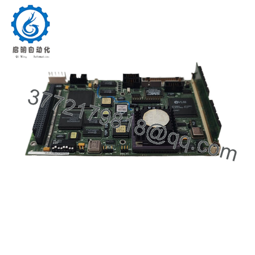
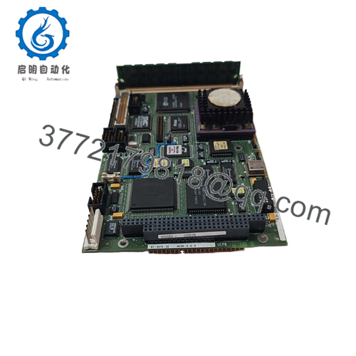
The GE DS200PTBAG1ABA is a Protection Termination Module (PTBA) installed in the P1 core of GE’s Mark V Speedtronic turbine control system. It serves as the critical signal termination point for flame detection, shaft speed monitoring, generator voltage/current sensing, and external trip signals — routing these to the TCEB and TCQE boards for turbine protection decisions. This board is essential for hardwired overspeed protection and combustion monitoring in industrial gas and steam turbine applications.As a New Surplus unit, this module represents strategic inventory for plants operating legacy Mark V systems. GE discontinued active production of many Mark V components, making genuine new surplus the only reliable alternative to refurbished units with questionable reliability. The Total Cost of Ownership (TCO) calculation heavily favors new surplus: a refurbished board might cost 20% less upfront, but capacitor aging and prior thermal stress create failure risks that could trigger $100,000+ in emergency downtime. This New Surplus unit delivers 10-15 years of service life with full warranty protection — a critical insurance policy for baseload power generation assets.
5. Installation & Configuration Guide
Stage 1: Pre-Installation (Prep & Safety)
- Lock-out/Tag-out: Isolate the Mark V cabinet from 125V DC control power and 24V I/O power. Verify zero energy state with a multimeter.
- Documentation: Photograph the existing DS200PTBAG1ABA module — capture DIP switch positions (if any), all cable labels, and wire routing.
- ESD Protocol: Attach grounded wrist strap to the cabinet earth bar. Static discharge can destroy sensitive signal conditioning circuits.
- Tool Preparation: Phillips screwdriver, torque screwdriver (set to 12 in-lb for terminal screws), flashlight, and wire labels.
Stage 2: Removal
- Cable Extraction: Starting with JVA (335V DC flame power), carefully extract all connectors. Note: JJS/T is typically unused — verify before removal.
- Terminal Block Release: Loosen the 72-pin terminal block screws evenly to prevent pin binding. Do NOT rock the board side-to-side.
- Board Extraction: Grasp the board by the faceplate handles. Pull straight out with steady pressure. Inspect backplane pins for bending or corrosion.
Stage 3: Installation (Clone & Seat)
- Jumper Configuration: Verify J1 jumper position — remove J1 to disable the TCEB horn alarm if noise elimination is required.
- Board Seating: Align the DS200PTBAG1ABA with the P1 core backplane. Press firmly until the board seats fully — the faceplate should sit flush against the chassis.
- Connector Replication: Reconnect JM, JN, JU, JV, JJR, and JVA exactly as photographed. The JVA connector carries 335V DC — double-check polarity.
Stage 4: Power-On & Testing
- Continuity Check: Verify no shorts between 24V rails and ground before applying power.
- Power-Up Sequence: Apply 125V DC control power first, then 24V I/O power. Observe LEDs on adjacent TCEB board.
- Signal Verification:
- Confirm flame detection signals register on the HMI
- Verify shaft speed readings match actual turbine RPM
- Test emergency trip circuit via simulation (if available)
- Documentation: Record serial number, installation date, and firmware version in the plant’s CMMS system.
6. Firmware/Software Versions & Upgrade Notes
The DS200PTBAG1ABA is a passive termination board with no onboard firmware or microprocessors. However, integration with the Mark V system requires firmware compatibility between the TCEB (P1 core) and TCQE (R1 core) boards it communicates with.
| Component | Firmware Consideration |
|---|---|
| TCEB Board | Must match the revision level expected by the <P1> |
| TCQE Board | Speed signal processing firmware must align with PTBA signal conditioning |
| Mark V Application Code | Ensure the control constants block recognizes PTBA revision ABA |
Critical Warning: When replacing a DS200PTBAG1ABA during a hardware swap, do NOT simultaneously upgrade TCEB or TCQE firmware. Changing both hardware and firmware in the same maintenance window creates compound failure risk. If the existing board runs with TCEB firmware V3.x, maintain that version until the new PTBA board is proven operational. Document the firmware revision of the old module before removal — Mark V systems can be sensitive to firmware jumps across multiple revision levels.

- DS200PTBAG1ABA
7. Frequently Asked Questions (FAQ)
Q: Why is this New Surplus unit priced higher than refurbished options?
A: Refurbished boards typically carry 30-day warranties and have unknown operational history — many have been thermally stressed in prior service. This New Surplus unit is factory-original with zero prior runtime, offering 10-15 years of expected service life and a 12-month warranty. The price delta reflects the elimination of catastrophic failure risk.
Q: Is the DS200PTBAG1ABA still manufactured by GE?
A: No. The Mark V Speedtronic series is in mature lifecycle phase with many components, including the DS200PTBAG1ABA, discontinued from active production. This is genuine New Surplus inventory — original OEM manufacturing, never deployed. For critical applications, we recommend a last-time-buy strategy to secure buffer stock before availability tightens further.
Q: Can I hot-swap this module while the turbine is running?
A: Absolutely not. The DS200PTBAG1ABA carries 335V DC flame detection power and critical trip circuit signals. Hot-swapping risks arc faults, false trips, and personnel injury. Always execute Lock-out/Tag-out procedures and de-energize the P1 core before replacement.
Q: Will my existing Mark V programming remain intact after replacement?
A: Yes. The PTBA is a termination board — it does not store application logic or control constants. Your programming resides in the TCEB, TCQE, and core processor boards. However, you must replicate the J1 jumper configuration exactly to maintain alarm horn behavior.
Q: What is your warranty coverage?
A: We provide a 12-month replacement warranty against manufacturing defects. This covers functional failure under normal operating conditions (-40°C to +70°C, nominal voltage ranges). Physical damage, ESD damage from improper handling, or voltage surge events are excluded. Each unit ships with a QC Test Report documenting full functional verification.
Q: How do I verify this is genuine GE and not counterfeit?
A: Each unit ships with OEM traceability documentation including the original GE packing slip reference and serial number verification. The board carries GE factory markings, date codes, and the characteristic blue solder mask of authentic Mark V components. We perform incoming inspection for counterfeit indicators including font inconsistencies, incorrect PCB layer counts, and anomalous component markings.


