
 WhatsApp: +86 16626708626
 Email:
 Phone: +86 16626708626
Description
Core Product Summary
The GE DS200SDCCG1AGD and DS215SDCCG1AZZ01B are Drive Control Cards (SDCC) from the Mark V / DIRECTO-MATIC 2000 series. These boards provide the primary control circuitry and software for AC2000, DC2000, and EX2000 drive and exciter applications.
The G1 group version supports full functionality across those drive families. The DS215 assembly includes factory-programmed configuration data in socketed memory chips, while the DS200 version ships with empty sockets for those devices. Both use three 16-bit microprocessors linked by dual-ported RAM and interface to other system boards through multiple PL connectors.
Key Technical Specifications
| Parameter | Specification |
|---|---|
| Product Type | Drive Control Card (SDCC) |
| Series / Platform | Mark V / DIRECTO-MATIC 2000 |
| Group | G1 (AC2000, DC2000, EX2000 applications) |
| Processors | 3 × 16-bit microprocessors with dual-ported RAM |
| Drive Control Processor (DCP) | 80C186 (U1) – outer loops, user interfaces, system functions |
| Motor Control Processor (MCP) | 80C196 (U21) – current regulators, motor-specific control |
| Co-motor Processor (CMP) | TMS320C25 DSP (U35) – math-intensive algorithms when required |
| Onboard Memory (DS215) | 4 × EPROM (factory configuration) + 1 × EEPROM (field parameters) |
| Diagnostics | 10 LEDs (BCD for faults 1–399; binary for 400–1023) |
| Manual | GEI-100029 |
Detailed Product Overview
The SDCC serves as the central processing element in GE AC2000, DC2000, and EX2000 drive systems. It executes the core control algorithms that regulate motor or exciter performance while managing communication and signal exchange with companion boards.
Three dedicated processors operate in parallel through dual-ported RAM. The Drive Control Processor handles outer regulating loops (speed, position), user interfaces, and higher-level system tasks. The Motor Control Processor manages inner current loops and technology-specific functions such as DC phase control or AC motion control. When algorithms exceed the MCP’s capacity, the Co-motor Processor (a digital signal processor) provides additional computational power for complex calculations.
The DS215 version is supplied with the five memory devices already installed and programmed. The DS200 version has empty sockets so that existing memory chips can be transferred during a replacement. This arrangement allows field retention of application-specific parameters stored in the EEPROM.
Eight PL connectors link the SDCC to power/interface boards, LAN communications cards (DS215SLCC or equivalent), drive terminal boards, and optional signal processor cards. Mounting provisions exist on the SDCC itself for selected auxiliary boards. Diagnostic LEDs continuously report operating status or fault codes, switching between BCD and binary encoding according to the fault number range.
Software configuration, parameter adjustment, and firmware loading require ST2000, the GE Control System Toolbox, or the LynxOS Drive Configurator. The board can also serve as a direct replacement for earlier 531X301DCC Drive Control Cards when the DS215 assembly (with memory devices) is specified.
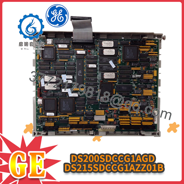
DS200SDCCG1AGD DS215SDCCG1AZZ01B
System Compatibility & Integration Requirements
| Item / Dependency | Verified Compatibility or Requirement | Practical Note |
|---|---|---|
| Drive families | AC2000, DC2000, EX2000 (G1 group) | Full-function G1 version |
| Power / Interface boards | DS200IMCP, DCI, SDCI, or DCFB | Via 1PL and 2PL |
| LAN Communications | DS215SLCC or 531X306LCC | Via 3PL; auxiliary mounting supported |
| Terminal boards | 531X305NTB or DS200STBA | Via 6PL and 8PL |
| Signal processing | 531X309SPC or DS200SPCB | Via 7PL (not present on G3) |
| Software tools | ST2000, GE Control System Toolbox, or LynxOS Drive Configurator | Required for configuration and memory operations |
| Memory devices | Factory EPROMs + field EEPROM (DS215) | Transfer existing chips when replacing with DS200 |
Dimensions, Mounting & Connection Notes
The SDCC mounts in the standard Mark V / DIRECTO-MATIC 2000 card rack or carrier. It provides mounting locations for auxiliary boards (LAN communications and signal processor cards). Connection is made exclusively through the eight designated PL connectors; no additional field wiring terminals are present on the card itself. Hardware jumpers (Berg-type and wire) are provided for application-specific options and must match the settings recorded on the original board or test data sheet.
FAQ
What is the GE DS200SDCCG1AGD / DS215SDCCG1AZZ01B?
It is a Drive Control Card (SDCC) that supplies the primary control circuitry and software for GE AC2000, DC2000, and EX2000 drives and exciters.
What is the difference between the DS200 and DS215 versions?
The DS215 assembly includes the five socketed memory chips (four factory EPROMs and one field EEPROM). The DS200 version ships with empty sockets so existing memory devices can be transferred.
Which processors are used on the SDCC?
Three 16-bit processors: an 80C186 Drive Control Processor, an 80C196 Motor Control Processor, and a TMS320C25 Co-motor Processor, all interconnected by dual-ported RAM.
Which drive applications does the G1 group support?
AC2000, DC2000, and EX2000 drive applications.
What diagnostic indication does the board provide?
A bank of ten LEDs displays fault codes in BCD format for faults 1–399 and binary format for faults 400–1023. Normal operation is shown by a sequential two-LED blink pattern.
What software is required for configuration?
ST2000, the GE Control System Toolbox, or the LynxOS Drive Configurator.
Can this card replace an older DCC?
Yes. When replacing a 531X301DCC, specify the DS215 version to ensure the memory chips are included.



