
 WhatsApp: +86 16626708626
 Email:
  Phone: +86 16626708626
Description
3. Key Technical Specifications
| Parameter | Value |
|---|---|
| Manufacturer | General Electric (GE) |
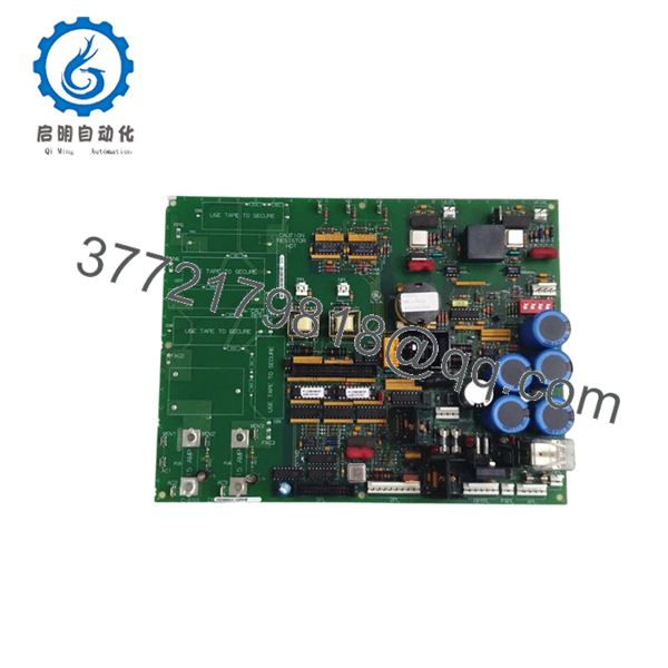
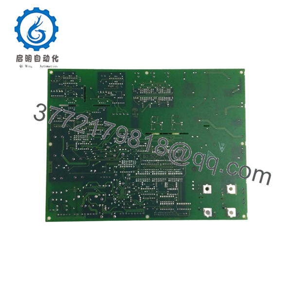
| Model Number | DS200SDCIG2AHB |
| Functional Type | SDCI DC Power Supply & Instrumentation Board |
| Product Family | Mark V DS200 |
| System Application | GE Speedtronic Mark V |
| Group Version | G2 |
| Interface Function | DC2000 Drive Interface |
| Logic Power Output | +5 VDC, 4 A |
| Auxiliary Output | ±15 VDC, 0.4 A |
| Additional Power | ±24 VDC |
| AC Supply Circuit | 115 VAC, 0.4 A |
| Jumper Configuration | JP1, JP2 |
| Switch Configuration | SW1 CT burden selection |
| Weight | Approximately 1 lb (0.45 kg) |
| Instruction Manual | GEI-100173 |
The board provides power circuits, SCR gating support, and instrumentation feedback functions for GE DC2000 and Mark V assemblies.
4. Product Introduction
GE DS200SDCIG2AHB is a Mark V SDCI DC Power Supply and Instrumentation Board used in GE Speedtronic turbine and drive control systems. It supplies logic power, instrumentation interfaces, and field control circuitry for DC2000 drive assemblies.
In field deployments of Mark V systems, the G2 variants appear frequently on systems using external field exciters. Engineers typically choose this board when maintaining installed DC2000 infrastructure because replacing an entire drive architecture during an outage usually costs more than preserving the existing control topology.
- DS200SDCIG2AHB
- DS200SDCIG2AHB
5. Installation & Configuration Guide
Stage 1: Pre-Installation Preparation (Estimated: 10 minutes)
⚠️ Safety First: Notify operations personnel of downtime. Verify process safe state. Apply lockout/tagout procedures. Wait at least 5 minutes for bus capacitor discharge.
Tools Required:
- ESD wrist strap
- PH1 screwdriver
- Fluke 115 multimeter
- Wire labels
- Smartphone for reference photos
Data Backup:
- Export available configuration data.
- Record drive settings.
- Photograph jumper positions and terminal routing.
- Capture SW1, JP1, and JP2 positions.
❗I have seen technicians skip the photos because “it’s only three jumpers.” Two hours later they are tracing wiring with a flashlight.
Stage 2: Removing the Old Module (Estimated: 5–8 minutes)
- Remove enclosure cover or bezel.
- Label all cables before disconnecting.
- Release rack retention tabs.
- Pull board straight out. Do not twist.
- Inspect connector fingers and backplane pins for contamination.
⚠️ Keep the original module nearby until startup succeeds.
Mark V racks have saved many projects because the old board became the troubleshooting reference.
Stage 3: Installing the New Module (Estimated: 5 minutes)
- Attach ESD strap before touching PCB.
- Confirm exact part number: DS200SDCIG2AHB.
- Configuration Clone (Crucial): Match JP1, JP2 and SW1 positions exactly.
- Insert board evenly into card guides.
- Confirm positive seating engagement.
- Reconnect cables with proper torque.
Self-Checklist
- DIPs and jumpers match
- Wiring secured
- Lock tabs engaged
- Connector fully seated
❗This is the most common rookie mistake, but it happens constantly. Take a picture before you pull it. I can’t stress this enough.
Stage 4: Power-On & Testing (Estimated: 10 minutes)
Pre-Power Check
Use a multimeter and verify no short exists on the 24 V rail.
Power Sequence
- Energize rack only.
- Observe LEDs and startup sequence.
- Verify communication response.
- Restore configuration if required.
- Perform dry I/O simulation.
LED Interpretation
- Green RUN = operating normally
- Red ERR = fault condition
⚠️ Troubleshooting Note: If communications fail after replacement, suspect jumper mismatch or firmware differences before assuming board failure.
Technical Pitfall & Survival Guide
❗Firmware Revision Mismatch
I have seen replacement boards arrive with revised firmware behavior and slightly different communication timing. One outage stretched into two days because a newer module revision changed communications behavior enough to trigger repeated timeout alarms.
Avoidance:
- Record firmware and board revision before removal
- Request revision matching during purchase
- Keep photos of labels and assembly suffixes
❗DIP Switch / Jumper Misconfiguration
The DS200SDCIG2AHB uses JP1, JP2 and SW1 configuration elements. Factory settings rarely match installed systems.
Take photos before removal.
❗Terminal Block / Wiring Differences
Even closely related board revisions can differ.
I’ve seen technicians wire from memory because “all DS200 boards look similar.” They don’t.
Verify wiring drawings.
❗Power Consumption
Do not assume rack loading remains unchanged.
Calculate total load and leave a 20% supply margin.
❗ESD Damage
This board is static sensitive. GE specifically identifies handling precautions.
I once watched an engineer unpack a control board during winter without a wrist strap. Powered it up and smoke immediately followed. That lesson cost several thousand dollars.
Keep these checks in mind and you’ll save yourself 90% of typical rework time.
SOP Quality Transparency
1. Inbound Inspection & Traceability
- Verify OEM labels and shipping documentation
- Inspect serial labels and anti-counterfeit markings
- Visual examination for scratches, corrosion, UV yellowing, or repair marks
- Audit included documentation and accessories
2. Live Functional Testing
Test environment:
- Genuine GE Mark V test rack
- Simulated DC2000 interface environment
Procedure:
- Power-on self-test
- LED status validation
- Communication handshake verification
- Signal simulation on I/O interfaces
- Continuous thermal run >24 hr
- Generate formal test report
Test videos and photos are available upon request.
3. Electrical Testing
- 500 V Megger insulation test (>10 MΩ)
- Ground continuity verification
- Hipot test when applicable
4. Firmware Verification
- Record firmware identification
- Photograph jumpers and switch positions
5. Final QC & Packaging
- Inspector signoff
- Anti-static ESD bag
- Bubble protection
- Heavy-duty corrugated packaging
- QC date labeling
Verified fully functional under load testing.
6. Frequently Asked Questions (FAQ)
Q1. Can I hot-swap this module?
No. Do not attempt it.
The DS200SDCIG2AHB was not designed for live insertion. Pulling the board under power risks damaging the backplane or creating transient faults inside the drive system.
Kill power first.
Q2. Is this model obsolete, and is it genuinely new?
Yes. Mark V hardware has been obsolete for years. Stock usually comes from New Surplus inventory or tested refurbished channels.
Ask for photos of labels and test reports.
Q3. What if DS200SDCIG2AHB is unavailable?
The closest alternatives are neighboring SDCI revisions, including DS200SDCIG2AFB and DS200SDCIG2ABA variants. Compatibility requires revision verification. Similar does not mean interchangeable.
Q4. Will I lose logic or programming when replacing it?
Typically no.
This board functions as power supply and instrumentation hardware rather than the primary controller. Still verify configuration storage location before shutdown.
Q5. Why is pricing lower than original GE factory pricing?
Because nearly all inventory now comes from surplus channels or inventory recovery programs rather than factory production.
That does not automatically mean used. Ask whether inventory is New Surplus or Refurbished.
Q6. Does the board require jumper configuration?
Absolutely.
JP1, JP2 and SW1 settings directly affect operation. Incorrect settings create startup faults that can waste hours during commissioning.
Q7. What warranty is realistic for obsolete control hardware?
One year is common for tested surplus inventory. Some suppliers provide longer repair warranties, but verify coverage details carefully.


