
 WhatsApp: +86 16626708626
 Email:
  Phone: +86 16626708626
Description
3. Key Technical Specifications
| Parameter | Value |
|---|---|
| Manufacturer | GE General Electric |
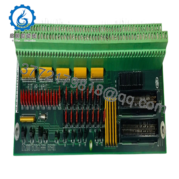
| Model | DS200TBCBG1A |
| Product Type | RTD and Analog Input Termination Module |
| Series | Mark V Speedtronic |
| Functional Acronym | TBCB |
| Functional Revision | A |
| Core Location | R5 Analog I/O Core |
| Total Inputs | 36 |
| Analog Inputs | 22 mA transducer channels |
| RTD Inputs | 14 three-wire RTD channels |
| Configurable Inputs | 8 channels switchable to 0–1 mA |
| Signal Routing | Communicates with TCCB board |
| Hardware Configuration | BJ1–BJ30 jumper settings |
| Mounting | Mark V I/O rack installation |
| PCB Coating | Standard industrial coating |
DS200TBCBG1A operates as a field termination module inside GE Mark V turbine systems and routes RTD and analog signals into the TCCB processing path.
4. Product Introduction
GE DS200TBCBG1A is a Mark V RTD and analog termination module used in GE Speedtronic turbine control systems. The board interfaces field-mounted transmitters and RTD devices with the control platform and routes signals into the R5 core processing path.
In field deployments of Mark V cabinets, this board commonly appears in gas and steam turbine systems where dozens of process signals enter the cabinet through a single termination layer. Engineers usually keep exact replacements on the shelf because redesigning signal interfaces during an outage creates unnecessary downtime exposure.
5. Installation & Configuration Guide
Stage 1: Pre-Installation Preparation
Estimated Time: 10 minutes
⚠️ Safety First: Notify operations personnel, place equipment into a safe state, perform lockout/tagout, and wait at least 5 minutes for stored energy discharge.
Tools Required
- ESD wrist strap
- PH1 screwdriver
- Fluke 115 multimeter
- Wire labels
- Smartphone for photos
Data Backup
- Export current control logic and configuration data.
- Record cabinet slot location.
- Photograph jumper positions BJ1–BJ30.
- Photograph all field wiring.
- Record cable labels.
Stage 2: Removing the Old Module
Estimated Time: 5 minutes
- Remove front panel access.
- Label all terminal wiring.
- Disconnect field wires carefully.
- Release board retaining hardware.
- Pull module straight outward.
- Inspect rack connectors and backplane condition.
⚠️ Keep the old board beside you until startup is complete.
I’ve watched technicians remove hardware and throw it into a spare-parts bin only to discover they forgot jumper details.
Stage 3: Installing the New Module
Estimated Time: 10 minutes
- Put on ESD protection.
- Verify DS200TBCBG1A revision matches removed hardware.
- Configuration Clone (Crucial): Replicate all jumper settings exactly.
- Pay close attention to BJ23–BJ30 conversion settings.
- Insert board evenly into slot guides.
- Confirm seating pressure and lock engagement.
- Reconnect field wiring.
Self-Checklist:
[ ] Jumpers match
[ ] Wiring secured
[ ] Locking tabs seated
❗This is the most common rookie mistake, but it happens constantly. Take a picture before you pull it. I can’t stress this enough.
Stage 4: Power-On & Testing
Estimated Time: 5 minutes
Pre-Power Check
Use a Fluke 115 multimeter and verify no short exists across the supply path.
Power-Up Sequence
- Power rack only.
- Observe cabinet LEDs.
- Verify communication status.
- Open programming tools.
- Verify expected signal values.
- Dry-run analog signal simulation.
⚠️ Troubleshooting Note: If field values appear shifted or incorrect, immediately inspect BJ jumper configuration before replacing additional hardware.
Veteran Survival Guide — Technical Pitfalls
❗ Firmware / Hardware Revision Mismatch
I have seen projects where a replacement board revision created two days of troubleshooting because nobody documented the original hardware revision. Record every suffix before removal.
❗ DIP Switch and Jumper Misconfiguration
This happens constantly. Somebody installs replacement hardware and forgets jumper positions.
Take a photo first. Every time.
❗ Terminal Wiring Assumptions
Even similar Mark V assemblies can use different connector layouts. Always verify wiring diagrams.
Do not wire from memory.
❗ Power Loading Oversight
Calculate rack power demand and leave at least 20% headroom. Small additions can create nuisance failures years later.
❗ ESD Damage
I once watched a technician swap a board in dry winter conditions without a strap. Immediate smoke after startup.
That was an expensive lesson.
Keep these checks in mind and you’ll save yourself 90% of typical rework time.
SOP Quality Transparency
1. Inbound Inspection & Traceability
- Verify OEM source records and shipment documentation
- Check serial labels and anti-counterfeit markings
- Inspect PCB for scratches, UV discoloration, corrosion, or repair marks
- Verify included certificates and accessories
2. Live Functional Testing
Testing performed on genuine GE Mark V cabinet hardware where available.
Procedure:
- Power-on self-test
- LED inspection
- Communication verification
- RTD simulation testing
- Analog input simulation
- Continuous runtime over 24 hours with temperature monitoring
- Test report generation
Photos and test videos available upon request.
3. Electrical Parameter Testing
- Insulation resistance using 500 V Megger (>10 MΩ)
- Ground continuity verification
- Fluke 115 electrical measurements
- Hipot testing where applicable
4. Firmware & Configuration Verification
- Hardware revision documentation
- Jumper setting photographic record
- Configuration backup
5. Final QC & Packaging
- QC sign-off
- ESD anti-static packaging
- Bubble-wrap protection
- Heavy-duty corrugated carton
- QC-passed inspection label with date
Verified fully functional under load testing.

- DS200TBCBG1A
6. Frequently Asked Questions (FAQ)
Q1: Can I hot-swap this module?
No.
Mark V systems were not designed around modern hot-swap architecture. Pulling hardware under power can damage the rack or create communication faults.
Kill power first.
Q2: Is DS200TBCBG1A obsolete?
Yes. OEM production support has ended and multiple industrial suppliers list it as discontinued or available primarily through surplus inventory channels.
Q3: Is New Surplus actually unused?
Usually yes.
New Surplus generally means inventory purchased for projects, OEM overstock, or cancelled installations that never entered operation. Verify packaging condition and testing documentation before purchase.
Q4: What is the direct replacement if stock runs out?
Replacement depends heavily on Mark V cabinet architecture and installed board revisions. Verify exact compatibility using GE documentation before assuming interchangeability.
Q5: Will removing this board erase programming?
No. DS200TBCBG1A is a termination board, not the primary controller.
Still, export backups first. After enough midnight shutdowns, you learn never to trust assumptions.
Q6: Why are market prices inconsistent?
Because inventory mostly comes from surplus channels now. Availability, condition, and revision level drive pricing much more than original OEM list values.
Q7: Why are analog values incorrect after replacement?
Start with jumper settings.
Eight channels can convert from 4–20 mA to 0–1 mA through hardware configuration. A mismatch here can waste hours of troubleshooting.


