
 WhatsApp: +86 16626708626
 Email:
  Phone: +86 16626708626
Description
3. Key Technical Specifications
| Parameter | Value |
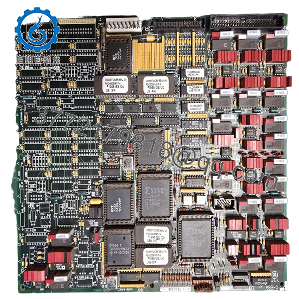
| Main Processor | Intel 80196 16-bit Microcontroller |
| Architecture | Mark V (Common) Core Processor |
| Revision Level | G8BED (Enhanced group with specific firmware mapping) |
| I/O Interface | IONET, ARCNET, and RS-232 serial communication |
| Memory | Volatile RAM and non-volatile EPROM sockets |
| Logic Supply | +5 V DC, +/-15 V DC via the TCEA board or backplane |
| Onboard Display | 7-segment LED for diagnostic codes and heartbeat |
| Isolation | Optical isolation for signal integrity across the IONET |
4. Product Introduction & Supply Chain Strategy
The GE DS200TCCBG8BED is the primary coordination board for the (Common) core in a Mark V Speedtronic system. It acts as the traffic controller, managing communications between the redundant , , and cores and the operator interface (HMI). Without a functional TCCB, the system loses its ability to synchronize data and report critical diagnostics, effectively blinding the turbine operators.
From a supply chain perspective, the TCCB is a “Single Point of Failure” component. Using a refurbished board in this position is high-risk; the age-related degradation of the 80196 processor and associated logic chips can lead to intermittent “bus hangs” that are notoriously difficult to troubleshoot. By choosing New Surplus, you secure a module with zero hours of thermal fatigue, ensuring maximum uptime and avoiding the $50,000+ daily losses associated with unplanned turbine trips.

- DS200TCCBG8BED
- DS200TCCBG8BED
5. Installation & Configuration Guide
Stage 1: Pre-Installation (Prep & Safety) Perform a full system data dump of the current Control Sequence Program (CSP). Execute LOTO on the control cabinet power. Ensure you have a grounded ESD wrist strap. Document the version numbers on the socketed EPROMs (U6 and U7) and the positions of all jumpers (JP1-JP15).
Stage 2: Removal Disconnect the ribbon cables from the 3PL, 4PL, and IONET ports. Carefully unscrew the board from the nylon standoffs. Use a card puller if necessary to ensure the board remains level, preventing damage to the pins on the underlying TCEA or backplane.
Stage 3: Installation (Clone & Seat) Transfer the site-specific EPROMs from the old board to the new DS200TCCBG8BED. Verify the orientation notch on each chip. Set the jumpers on the new board to be an exact mirror of the original unit. Press the board firmly onto the standoffs until you feel the connectors click into place.
Stage 4: Power-On & Testing Re-energize the core. Watch the 7-segment LED. A successful boot sequence typically ends in a “4” or a pulsing decimal point indicating the heartbeat is active. Use the “VIEW” or “TABLE” tools on your HMI to verify that the core is communicating with the , , and cores.
6. Firmware/Software Versions & Upgrade Notes
- EPROM Requirements: The DS200TCCBG8BED usually requires the U6 and U7 chips to be moved from the old board. These chips contain the specific application code for your turbine.
- Revision Matching: The “G8BED” version is a specific revision level. While it may replace older G-group boards, it is critical to verify that your “CONFIG.DAT” files are updated if you are moving to a newer revision than what was originally installed in 1990s-era cabinets.
- Upgrade Risks: Never attempt to flash or change firmware while the turbine is online. A mismatch between the TCCB and the redundant core processors will cause a communication lockout.
7. Frequently Asked Questions (FAQ)
Is this board “New Surplus” or “Refurbished”? This is 100% New Surplus. It has never been installed in a working rack or subjected to the high-heat environment of a turbine control room. We do not sell “refurbished” or “repaired” TCCB boards because the reliability of the central processor is too critical for second-hand risks.
Does this board control the actual turbine speed? The TCCB coordinates the data, but the , , and cores handle the actual protective algorithms. However, if the TCCB fails, you lose the ability to change setpoints, acknowledge alarms, or view real-time data, making safe operation nearly impossible.
What do the error codes on the 7-segment display mean? Codes like “E1” or “E2” typically point to a failure during the Power-On Self-Test (POST), often related to an EPROM seating issue or a RAM failure. A blank display usually indicates a 5V power supply problem from the backplane.
Can I use a G1 or G2 revision instead of this G8? Generally, no. GE revisions are often upward-compatible, but jumping from a very early G-revision to a G8BED requires verifying that the jumper headers and communication speeds are compatible with your existing Mark V firmware release.
What is the shelf-life of this board? Stored in its original ESD-safe packaging in a climate-controlled environment, this board has an indefinite shelf life. We recommend keeping at least one New Surplus TCCB in your on-site “Insurance” inventory.


