
 WhatsApp: +86 16626708626
 Email:
  Phone: +86 16626708626
Description
3. Key Technical Specifications
| Parameter | Value |
|---|---|
| Manufacturer | General Electric (GE) |
| Model Number | DS200TCEAG1B |
| Functional Acronym | TCEA |
| Product Type | Emergency Overspeed Board |
| Series | Mark V Speedtronic |
| Primary Function | Turbine overspeed protection |
| Secondary Function | Flame detection trip processing |
| Processor Type | Intel 80196 Microprocessor |
| Memory Type | Multiple PROM modules |
| Jumper Count | 30 configurable jumpers |
| Fuse Count | 3 onboard fuses |
| Network Interface | IONet daisy-chain connectors |
| Connector Types | Bayonet and board-edge connectors |
| System Location | <P> Protection Core |
| Redundancy Support | TMR-compatible architecture |
| Diagnostic Functions | Overspeed, flame detection, synchronization |
| Protective Coating | Standard industrial PCB coating |
| Mounting Method | Panel/rack mounted |
| Application | Gas, steam, and turbine protection systems |
| Condition Options | New Original, New Surplus, Refurbished (tested) |
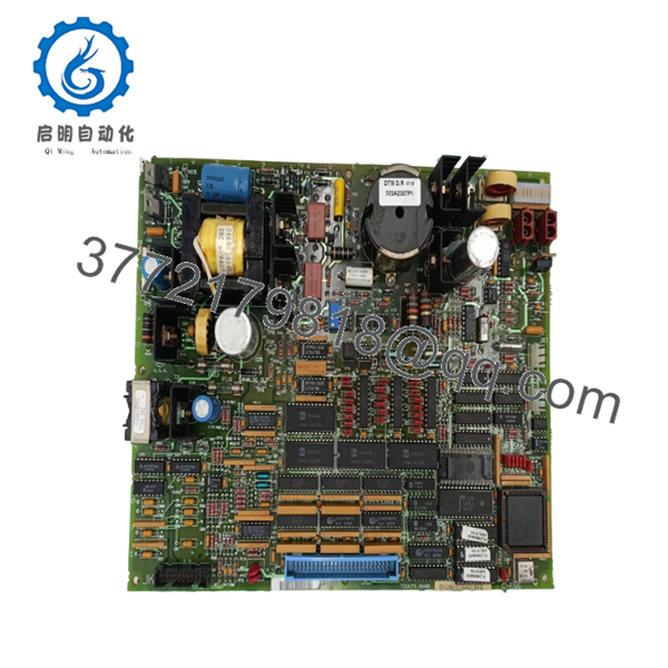
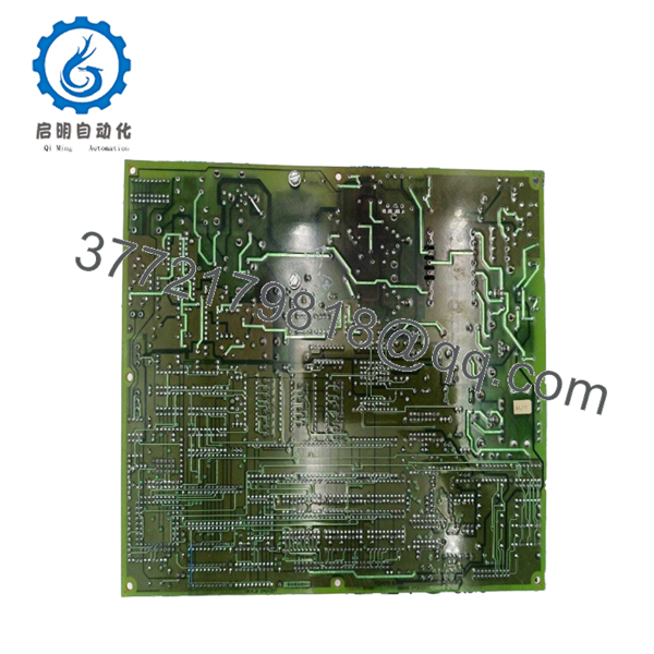
The DS200TCEAG1B is an Emergency Overspeed Board used in GE Mark V turbine control systems. It monitors turbine overspeed conditions and flame detection trip logic and initiates shutdown sequences when protection thresholds are exceeded.
4. Product Introduction
The GE DS200TCEAG1B is an Emergency Overspeed Board designed for the Mark V Speedtronic turbine control platform. It operates inside the protection core and supervises turbine overspeed conditions, flame trip logic, and synchronization-related protection functions.
In real-world turbine cabinets, the TCEA board is one of the last electronic protection layers before a trip command is issued. Engineers usually replace this board cautiously because jumper configuration, firmware alignment, and IONet topology directly affect shutdown integrity and protection timing.

- DS200TCEAG1B
- DS200TCEAG1B
5. Installation & Configuration Guide
Stage 1: Pre-Installation Preparation (Estimated Time: 10 Minutes)
⚠️ Safety First
- Notify operations before taking the turbine control system offline.
- Bring the turbine into a verified shutdown state.
- Apply lock out/tag out procedures to all related power feeds.
- Wait at least 5 minutes for stored energy inside the cabinet to discharge.
- Verify zero voltage using a Fluke 115 or equivalent multimeter.
Tools Required
- ESD wrist strap
- PH1 screwdriver
- Multimeter
- Wire labels
- Smartphone for documentation photos
- Flashlight
Data Backup
- Export existing Mark V configuration data.
- Record all protection-core board locations.
- Photograph:
- Jumper positions
- Bayonet connector routing
- IONet cable placement
- Protection core layout
- Document all board revision levels.
❗ Mark V protection cores often contain undocumented field modifications from previous outages. Never assume the cabinet still matches the original drawings exactly.
Stage 2: Removing the Old Module (Estimated Time: 5 Minutes)
- Remove the cabinet protective cover.
- Label every connector before disconnecting it.
- Disconnect bayonet connectors carefully while supporting the PCB.
⚠️ Important
Do not pull on the cable itself. Bayonet connectors can stress the board mechanically, and I’ve seen older Mark V boards crack near the connector edge from rushed removal.
- Release mounting hardware evenly.
- Pull the board straight outward.
Inspect the Cabinet Area
Check for:
- Loose hardware
- Fuse discoloration
- Carbon tracking
- Dust accumulation
- Heat damage near connectors
⚠️ Keep the old board
Do not return or discard the original board until startup and trip testing complete successfully.
Stage 3: Installing the New Module (Estimated Time: 10 Minutes)
- Wear a grounded ESD strap before handling the replacement board.
- Verify:
- Exact model number
- Revision suffix
- Connector arrangement
- Protection-core compatibility
❗ Configuration Clone (Critical)
The DS200TCEAG1B contains approximately 30 jumper settings used for hardware configuration.
This is where people get into trouble.
I’ve personally seen maintenance teams replace a TCEA board successfully from a hardware standpoint, but leave one jumper in factory default position. The turbine started, but overspeed diagnostics failed during permissive checks and delayed startup for nearly an entire shift.
Before removal:
- Photograph every jumper clearly
- Label unusual settings
- Verify against the cabinet drawings
- Install the board evenly into position.
- Secure mounting hardware carefully.
- Reconnect all bayonet and board-edge connectors.
Self-Checklist
- Jumpers duplicated exactly
- Connectors fully seated
- Fuses verified
- Grounding intact
- No loose hardware inside cabinet
Stage 4: Power-On & Testing (Estimated Time: 15 Minutes)
Pre-Power Check
- Verify no short circuits exist on supply rails.
- Check fuse continuity before energizing.
- Confirm cabinet grounding continuity.
Power-On Procedure
- Energize the control cabinet only.
- Observe startup diagnostics and status LEDs.
- Verify communication through IONet.
- Confirm:
- Overspeed diagnostics healthy
- Flame detection inputs healthy
- Synchronization diagnostics normal
- Perform dry-run protection testing before returning the turbine to service.
⚠️ Firmware Revision Mismatch
Mark V systems are sensitive to revision differences.
I’ve seen newer replacement boards communicate correctly at first, then generate intermittent protection faults during startup sequencing because firmware revisions differed slightly from adjacent protection-core hardware.
Always verify:
- Existing firmware levels
- PROM versions
- Associated protection-core board revisions
before installation.
⚠️ Jumper Configuration Errors
This is probably the single most common failure point during TCEA replacement.
Factory-default jumper settings rarely match live plant configurations. Take photos before removal. Seriously.
⚠️ IONet Communication Issues
If the protection core loses IONet communication after replacement:
- Check daisy-chain connectors
- Verify node continuity
- Inspect cable shielding
- Confirm connector seating
One loose bayonet connector can create hours of unnecessary troubleshooting.
⚠️ ESD Handling
Always use grounding protection.
I once watched a technician carry a spare Mark V protection board across a dry turbine deck in winter without an ESD strap. The board powered up initially, then failed during diagnostics ten minutes later. Static damage is not always immediate.
Keep these checks in mind and you’ll save yourself 90% of typical rework time.
6. Frequently Asked Questions (FAQ)
Q1: Can the DS200TCEAG1B be hot-swapped?
No.
This board is part of the turbine protection system and should never be removed under power. Hot-swapping can interrupt protection logic and potentially damage the protection core or backplane.
Always isolate power completely before replacement.
Q2: Is the DS200TCEAG1B obsolete?
Yes.
The GE Mark V platform is considered legacy hardware, although it remains widely deployed in gas and steam turbine facilities globally. Most available inventory now comes from surplus channels, refurbishment programs, and outage spare stock.
Q3: What exactly does this board protect against?
The DS200TCEAG1B primarily handles:
- Turbine overspeed protection
- Flame detection trip processing
- Synchronization-related protection logic
If overspeed thresholds are exceeded, the board initiates protective shutdown actions.
Q4: Why are there so many jumpers on this board?
The 30 jumper settings configure:
- Protection-core assignment
- System location
- Communication routing
- Hardware operating parameters
Honestly, jumper mistakes are one of the biggest causes of failed startup after replacement.
Q5: Will replacing the board erase my turbine logic?
Normally, no.
The TCEA board processes protection functions, but overall application logic generally resides elsewhere in the Mark V architecture. Still, always back up configuration data before shutdown.
Never trust undocumented legacy systems.
Q6: What is the most common installation mistake?
Incorrect jumper duplication.
I’ve seen experienced engineers assume factory defaults were acceptable. They weren’t. One misplaced jumper caused a turbine permissive failure that delayed startup for hours.
Photograph every jumper before removal.
Q7: What testing should be completed before shipment?
A proper QC process should include:
- OEM traceability verification
- Serial number inspection
- Visual inspection for corrosion or repair marks
- Fuse continuity testing
- Power-on testing using a compatible Mark V rack
- IONet communication verification
- PROM verification
- Insulation resistance testing using a 500 V Megger
- Burn-in testing under load for at least 24 hours
- ESD-safe packaging and QC sign-off
Verified fully functional under load testing. Test reports and startup videos should be available upon request.



