
 WhatsApp: +86 16626708626
 Email:
  Phone: +86 16626708626
Description
3. Key Technical Specifications
| Parameter | Value |
|---|---|
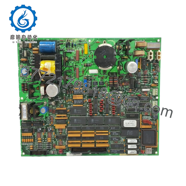
| Manufacturer | General Electric |
| Model Number | DS200TCEAG1BSF |
| Product Type | Emergency Overspeed Board |
| System Platform | GE Speedtronic Mark V |
| Board Function | Overspeed and flame trip monitoring |
| Processor | Single onboard microprocessor |
| Memory Type | Multiple PROM modules |
| Protection Components | 3 onboard fuses |
| Jumper Count | 30 configurable jumpers |
| Connector Type | Dual bayonet connectors |
| Installation Location | P-Core of Mark V panel |
| Application | Turbine shutdown and trip protection |
| Weight | Approximately 0.8 kg |
| Operating Role | Protection core / main trip circuit |
The DS200TCEAG1BSF operates inside GE Mark V turbine systems as an Emergency Overspeed Board responsible for monitoring overspeed and flame trip conditions and initiating protective shutdown logic.
4. Product Introduction
GE DS200TCEAG1BSF is an Emergency Overspeed Board designed for the GE Speedtronic Mark V turbine control platform. The board resides in the protection section of the control cabinet and processes overspeed and flame detection trip signals to initiate controlled shutdown actions before turbine damage occurs.
In field deployments of gas and steam turbine systems, this board becomes a critical component because the shutdown chain depends on it behaving predictably. The onboard microprocessor architecture, PROM modules, trip relays, and configurable jumpers allow the board to support site-specific shutdown logic while maintaining compatibility with existing Mark V installations.
- DS200TCEAG1BSF
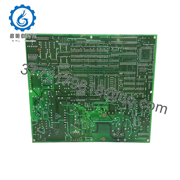
- DS200TCEAG1BSF
5. Installation & Configuration Guide
Stage 1: Pre-Installation Preparation (Estimated: 10 minutes)
⚠️ Safety First: Notify operations personnel of downtime. Confirm turbine safe-state conditions. Apply lockout/tagout procedures. Remove cabinet power. Wait a minimum of 5 minutes for discharge of stored energy.
Overspeed circuits are part of protection architecture. Treat shutdown circuits carefully.
Tools Required
- ESD wrist strap
- PH1 screwdriver
- Fluke 115 multimeter
- Wire labels
- Smartphone for photographs
- ESD work mat
Data Backup
- Export current Mark V configuration files.
- Record panel and slot locations.
- Photograph all bayonet connector locations.
- Photograph jumper positions.
- Document PROM module orientation and placement.
PROM positions matter.
I have watched engineers spend hours troubleshooting because two PROM modules were swapped.
Stage 2: Removing the Old Module (Estimated: 8 minutes)
- Remove cabinet panel cover.
- Label all connectors.
- Disconnect bayonet connectors carefully.
- Remove retaining hardware.
- Pull board straight outward.
⚠️ Never twist or flex the board.
Inspect:
- Connector pins
- Fuse condition
- Dust contamination
- Oxidation
- Backplane condition
⚠️ Keep the old board nearby until commissioning succeeds.
Stage 3: Installing the New Module (Estimated: 10 minutes)
- Wear ESD protection before handling electronics.
- Verify exact part number: DS200TCEAG1BSF
- Compare board revision markings.
- Transfer PROM modules if required.
- Install board fully and verify seating.
Configuration Clone (Crucial):
Replicate:
- jumper settings
- PROM placement
- connector orientation
- field modifications
This is the most common mistake.
Take pictures before removal.
I cannot stress this enough.
Self-Checklist
[ ] Jumper positions match
[ ] PROM modules match
[ ] Wiring secured
[ ] Connectors seated
[ ] Mounting hardware secure
Stage 4: Power-On & Testing (Estimated: 10–15 minutes)
Pre-Power Check
Using a Fluke 115:
- Verify no short across supply rails
- Confirm grounding continuity
- Confirm connector seating
Power sequence:
- Power rack only.
- Observe startup indicators.
- Connect engineering station.
- Verify board communication.
- Verify trip monitoring status.
- Perform dry-run signal simulation.
⚠️ Troubleshooting Note: Solid fault conditions after startup frequently point toward jumper errors or PROM installation issues rather than hardware failure.
I have watched maintenance teams replace perfectly good boards because PROM modules shifted one socket.
Technical Pitfall & Survival Guide
❗ Firmware Revision Mismatch
Legacy Mark V systems can be extremely revision-sensitive.
I once saw a shutdown board replacement create unexplained trip faults for two days. Firmware and PROM revisions differed slightly from the installed cabinet configuration.
Avoidance:
- Record firmware revisions
- Document PROM versions
- Request matching revision ranges
❗ DIP Switch / Jumper Misconfiguration
This mistake happens constantly.
Take a picture before removing anything.
Factory defaults almost never match plant settings.
❗ Terminal Block / Wiring Incompatibility
GE revisions occasionally introduce subtle connector or termination differences.
Verify:
- connector locations
- shielding
- grounding
- wiring drawings
Never wire from memory.
❗ Power Draw Specifications
Calculate cabinet loading.
Leave at least a 20% power margin.
Protection boards do not consume major current individually, but overloaded cabinets create strange intermittent faults.
❗ Electrostatic Discharge (ESD)
I watched an engineer grab a replacement board during winter outage work without an ESD strap.
Powered it.
Smoke immediately.
That became an expensive lesson.
Use:
- Grounded wrist strap
- ESD-safe work mat
- Anti-static handling procedures
Keep these checks in mind and you’ll save yourself 90% of typical rework time.
SOP Quality Transparency
1. Inbound Inspection & Traceability
- OEM packing verification
- Serial number recording
- Anti-counterfeit checks
- Surface inspection
- Corrosion inspection
- UV discoloration inspection
- Accessory verification
2. Live Functional Testing
Testing environment:
- Genuine GE Mark V test rack
Testing sequence:
- Power-on self-test
- LED inspection
- Communication verification
- Overspeed signal simulation
- Trip output verification
- Continuous operation >24 hours
- Thermal monitoring
Official test report generated.
Test videos and photographs available upon request.
3. Electrical Parameter Testing
- 500 V Megger insulation resistance >10 MΩ
- Ground continuity verification
- Hipot testing where applicable
4. Firmware & Configuration Verification
- Firmware documentation
- PROM revision recording
- Jumper position photographs
5. Final QC & Packaging
- QC inspector sign-off
- Anti-static ESD packaging
- Bubble wrap protection
- Heavy-duty corrugated carton
- QC Passed label with inspection date
Board functionality verified under sustained load conditions.
6. Frequently Asked Questions (FAQ)
Q1: Can I hot-swap DS200TCEAG1BSF?
No.
Do not attempt it.
This board sits directly in turbine protection architecture. Hot-swapping can damage control hardware and create false trip conditions.
Q2: Is DS200TCEAG1BSF obsolete?
Yes.
Mark V hardware is legacy equipment. Available inventory generally consists of New Surplus or tested refurbishment stock. Availability changes frequently.
Q3: Why are PROM modules important?
PROM modules contain firmware and operating instructions used by the onboard processor. During replacement they may require transfer from the existing board. Incorrect placement creates startup failures and nuisance trip events.
Q4: Is there a direct replacement?
Not automatically.
GE Mark V systems rely heavily on exact board and revision matching. Verify OEM documentation before substitution.
Q5: Will replacing this board erase plant logic?
Usually no.
This board handles protection functions and trip processing. System logic generally resides elsewhere. Still, always create backups before shutdown.
Q6: Why is New Surplus pricing lower than historical OEM pricing?
Most inventory now comes from plant shutdown stock, warehouse surplus, and discontinued inventory channels.
Request:
- serial verification
- actual board photographs
- test reports
- warranty documentation
before purchase.
Q7: What installation mistake causes the most rework?
PROM placement and jumper settings.
At 2 AM every PROM module suddenly looks identical. Photos taken before removal prevent long troubleshooting nights.


