
 WhatsApp: +86 16626708626
 Email:
  Phone: +86 16626708626
Description
3. Key Technical Specifications
| Parameter | Value |
|---|---|
| Model Number | DS200TCEAG1BTF |
| Manufacturer | GE General Electric |
| Product Type | Emergency Overspeed Board |
| Series | GE Speedtronic Mark V |
| Functional Abbreviation | TCEA |
| Primary Function | Overspeed and flame trip processing |
| Processor | Intel 80196 microprocessor |
| Fuse Count | 3 onboard fuses |
| Jumper Count | 30 configurable jumpers |
| Connectors | 2 bayonet connectors |
| Memory Type | PROM / EPROM module support |
| PCB Coating | Normal coating |
| Functional Revision 1 | B |
| Functional Revision 2 | T |
| Artwork Revision | F |
| Product Status | Legacy / Discontinued |
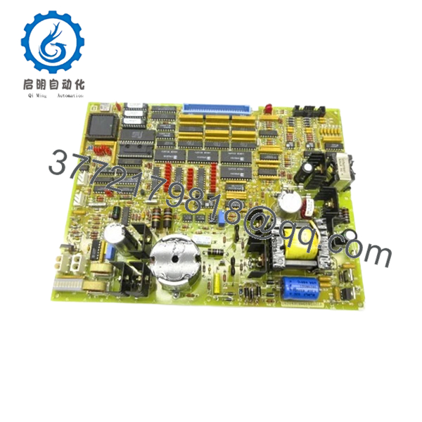
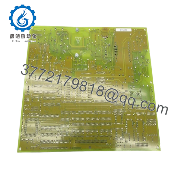
The DS200TCEAG1BTF uses an onboard microprocessor and PROM architecture for handling emergency overspeed protection logic. It also includes configurable jumper hardware and onboard fuse protection.
4. Product Introduction
The GE DS200TCEAG1BTF is an Emergency Overspeed Board used within GE Speedtronic Mark V gas turbine control systems. Its primary function is to process overspeed and flame trip signals and initiate protective shutdown actions when speed thresholds exceed configured limits.
In field deployments of Mark V systems, TCEA boards sit directly in the protection path. This is not a board you treat as a simple I/O card. If it fails, the turbine can trip unexpectedly or fail startup checks. Plants with aging Mark V assets usually keep validated spare inventory because exact revision matching becomes difficult years after OEM production ended.
- DS200TCEAG1BTF
- DS200TCEAG1BTF
5. Installation & Configuration Guide
Stage 1: Pre-Installation Preparation (Estimated Time: 10 minutes)
⚠️ Safety First: Notify operations of downtime. Verify turbine shutdown and safe process state. Apply lock out/tag out procedures. Wait at least 5 minutes for cabinet power and capacitor discharge.
Tools Required
- ESD wrist strap
- PH1 screwdriver
- Fluke 115 multimeter
- Wire labels
- Smartphone for photos
- Flashlight
Data Backup
- Export control settings where available.
- Record active alarms and fault history.
- Photograph all cable locations.
- Photograph jumper positions.
- Record PROM locations and revision labels.
⚠️ TCEA boards use PROM modules and jumper configurations. Missing one detail can create a long troubleshooting session later.
Stage 2: Removing the Old Module (Estimated Time: 5–10 minutes)
Steps:
- Remove cabinet access covers.
- Label every cable before disconnecting.
- Disconnect bayonet connectors carefully.
- Remove retaining hardware.
- Pull board straight out.
Inspect:
- Bent pins
- Connector wear
- Corrosion
- Dust buildup
- Heat damage
⚠️ Keep the old board nearby.
I’ve watched technicians discard the old board and later discover PROM orientation was undocumented.
Stage 3: Installing the New Module (Estimated Time: 10 minutes)
Steps:
- Wear grounded ESD protection.
- Verify exact model: DS200TCEAG1BTF
- Configuration Clone (Crucial): Match every jumper position exactly.
- Transfer PROM modules if required.
- Insert board evenly into guides.
- Reconnect bayonet connectors carefully.
Self-Checklist:
- Jumpers match
- PROM modules transferred correctly
- Connectors secure
- Board seated fully
❗This is the most common rookie mistake, but experienced engineers do it too. Pulling a board and assuming jumper defaults are correct creates unnecessary downtime.
The TCEA board contains approximately 30 jumper locations. Photograph everything before removal.
Stage 4: Power-On & Testing (Estimated Time: 10–15 minutes)
Pre-Power Check
Use a multimeter and verify no short exists on the 24 V rail.
Power sequence:
- Power cabinet only.
- Observe startup indicators.
- Connect engineering workstation.
- Review alarms.
- Verify overspeed signal health.
- Perform dry-run testing.
⚠️ Troubleshooting Note: If startup immediately generates protection faults, verify PROM transfer orientation and jumper settings.
I’ve seen outages stretch into a second shift because replacement boards arrived without PROM modules installed. Hardware matched. Firmware did not.
6. Frequently Asked Questions (FAQ)
Q1. Can I hot-swap this module?
No.
Do not hot-swap the DS200TCEAG1BTF. This board sits in a turbine protection chain. Pulling it under power risks backplane faults and protection logic issues.
Kill power first.
Q2. Is DS200TCEAG1BTF obsolete?
Yes.
This is a legacy GE Speedtronic Mark V component. Most current inventory comes from surplus warehouses or refurbished tested stock because OEM production ended years ago.
Q3. Do I need to move PROM modules from the old board?
Often yes.
Replacement boards frequently arrive without the original PROM modules installed. The PROM devices contain operating instructions and firmware used by the onboard processor. Using the existing PROMs often preserves behavior consistency.
I’ve seen projects sit offline for hours because a technician assumed firmware came preloaded.
Q4. Does the BTF suffix matter?
Absolutely.
GE suffixes identify revision changes. In Mark V systems, revision differences can affect timing behavior, firmware compatibility, and hardware operation. Treat the suffix as a compatibility requirement—not a cosmetic change.
Q5. Will I lose programming logic during replacement?
Usually no.
The TCEA board handles overspeed processing functions. Application logic normally resides elsewhere in the control architecture. Even so, always create backups before shutdown.
Assumptions become expensive during outages.
Q6. How are boards tested before shipment?
Standard workflow:
Inbound Inspection & Traceability
- Source verification
- Serial inspection
- Anti-counterfeit checks
- Corrosion and rework inspection
Live Functional Testing
- Testing on compatible GE hardware where available
- Power-up verification
- Communication testing
- Signal simulation
- Continuous operation >24 hours
Electrical Testing
- 500 V insulation resistance testing (>10 MΩ)
- Ground continuity verification
- Hipot testing if required
Firmware & Configuration Verification
- Revision recording
- PROM documentation
- Jumper configuration backup
Final QC
- Inspector sign-off
- ESD packaging
- Bubble wrap protection
- Heavy-duty shipping carton
Test videos and photos are available upon request.
Q7. What installation mistake causes the most downtime?
❗PROM transfer mistakes and jumper mismatches.
I once watched an engineer replace a board, power up the cabinet, and spend six hours chasing faults. The issue was not the replacement board. One PROM module was rotated incorrectly.
Keep these checks in mind and you’ll save yourself 90% of typical rework time.


