
 WhatsApp: +86 16626708626
 Email:
  Phone: +86 16626708626
Description
3. Key Technical Specifications
| Parameter | Value |
|---|---|
| Manufacturer | GE General Electric |
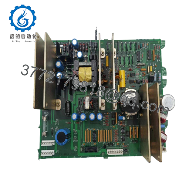
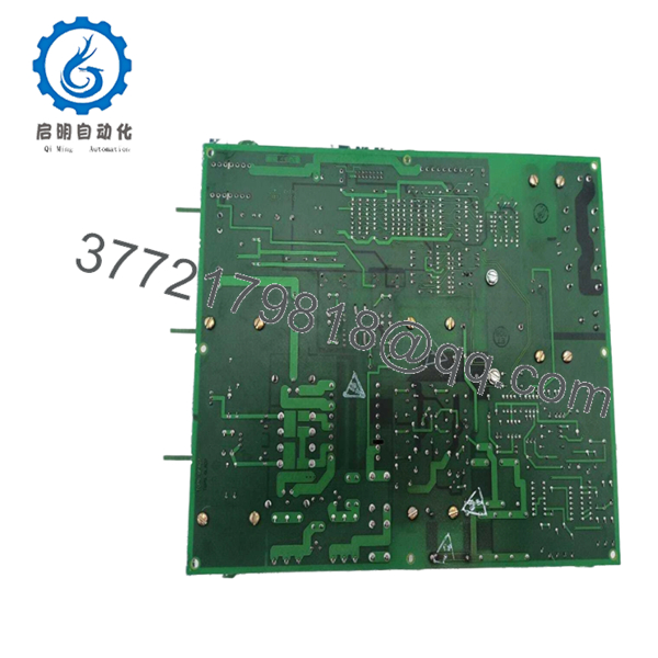
| Model Number | DS200TCPSG1A |
| Functional Acronym | TCPS |
| Product Type | DC Input Power Supply Board |
| System Family | Mark V Speedtronic |
| Application | Gas, steam, and turbine control systems |
| Functional Revision | A |
| PCB Coating | Standard coating |
| Input Source | 125 VDC from TCPD board |
| Connectors | 2PL, J1, JC, JP1, JP2, X1 |
| Fuse Count | 3 onboard protection fuses |
| Signal Conditioning | Included |
| Installation Location | R Core and I/O cores |
| Approximate Weight | 1–3 kg depending on packaging source |
The DS200TCPSG1A converts 125 VDC power from the PD/TCPD section into operating voltages used by processor circuitry, RTD supplies, mA outputs, and field-level functions inside Mark V systems.
4. Product Introduction
GE DS200TCPSG1A is a TCPS DC Input Power Supply Board used in the GE Mark V Speedtronic turbine control platform. Its primary role is voltage conversion and distribution for processor and I/O subsystems operating inside turbine control assemblies.
In field deployments of Mark V systems, TCPS boards often become replacement priorities during lifecycle extension projects. Plants usually replace the board instead of redesigning a running turbine control architecture because outage windows rarely justify a full migration to newer hardware. The board contains onboard signal conditioning and multiple protected outputs for system support functions.

- DS200TCPSG1A
- DS200TCPSG1A
5. Installation & Configuration Guide
Stage 1: Pre-Installation Preparation
Estimated time: 10 minutes
⚠️ Safety First: Notify operations personnel. Confirm process safe state. Apply lockout/tagout. Wait 5 minutes minimum for bus capacitors to discharge.
Tools Required
- ESD wrist strap
- PH1 screwdriver
- Fluke 115 multimeter
- Wire labels
- Smartphone camera
- Flashlight for rack inspection
Data Backup
- Export controller configuration where available.
- Record power supply settings.
- Photograph connector locations.
- Capture jumper positions.
- Record wiring orientation.
❗I have seen technicians skip the photo step because they thought connector placement was obvious. Three hours later they were tracing cables one by one.
Stage 2: Removing the Old Module
Estimated time: 5–8 minutes
- Remove panel cover.
- Label and disconnect all field wiring.
- Release board retaining tabs.
- Pull board straight out. Do not angle the extraction.
- Inspect edge connectors and backplane contacts.
⚠️ Do not discard the old board immediately.
Keep it beside the rack during startup. It becomes your wiring reference if troubleshooting starts.
Stage 3: Installing the New Module
Estimated time: 5 minutes
- Connect ESD strap before touching the board.
- Verify exact part number: DS200TCPSG1A.
- Configuration Clone (Crucial): Replicate all jumper and switch positions.
- Install evenly into card guides.
- Confirm locking tabs engage completely.
- Reconnect wiring with proper torque.
Self-Checklist
- Wiring secured
- Jumpers match original
- Tabs locked
- Connector fully seated
❗This is the most common rookie mistake, but it keeps happening. Take the picture before removal.
Stage 4: Power-On & Testing
Estimated time: 10 minutes
Pre-Power Check
Use a Fluke 115 and verify no short exists on DC rails.
Power Sequence
- Energize rack only
- Observe LEDs and startup sequence
- Verify communication activity
- Confirm operating voltages
- Simulate I/O operation where possible
⚠️ Troubleshooting Note: If startup faults occur after replacement, inspect jumper positions and verify board revision before assuming failure.
Technical Pitfall & Survival Guide
❗Firmware Revision Mismatch
Mark V revisions occasionally behave differently between production runs.
I watched one outage drag into day two because a newer board revision caused timing differences that generated communication faults.
Avoidance:
- Record revision labels before removal
- Request matching hardware revisions
- Photograph all board identification labels
❗DIP Switch / Jumper Errors
Factory settings rarely match field settings.
Take a photo before pulling the board. I can’t stress this enough.
❗Terminal Wiring Assumptions
Even GE boards sharing DS200 prefixes can route connectors differently.
Do not wire from memory.
Check drawings.
❗Power Consumption
Always calculate rack loading.
Leave at least a 20% power margin. Power supplies fail quietly before they fail completely.
❗Electrostatic Discharge
I once watched an engineer unpack a control board in winter with no wrist strap. The board powered up once and immediately released smoke.
That lesson cost thousands.
Use an ESD mat and grounded wrist strap.
Keep these checks in mind and you’ll save yourself 90% of typical rework time.
SOP Quality Transparency
1. Inbound Inspection & Traceability
- Verify OEM packing documentation
- Check serial labels and anti-counterfeit markings
- Inspect for scratches, corrosion, UV discoloration, or rework marks
- Audit included certificates and manuals
2. Live Functional Testing
Test Environment:
- Genuine GE Mark V rack
- Simulated turbine I/O environment
Procedure:
- Power-on sequence verification
- LED status inspection
- Communication handshake verification
- I/O simulation testing
- Continuous operation >24 hr with thermal monitoring
- Test report generation
Photos and startup videos available upon request.
3. Electrical Parameter Testing
- 500 V Megger insulation test (>10 MΩ)
- Ground continuity verification
- Hipot testing when required
4. Firmware & Configuration Verification
- Record revision level
- Photograph jumpers and labels
5. Final QC & Packaging
- Inspector sign-off
- Anti-static ESD packaging
- Bubble protection
- Heavy-duty corrugated box
- QC date labeling
Verified fully functional under load testing.
6. Frequently Asked Questions (FAQ)
Q1. Can I hot-swap this module?
No.
Do not remove a TCPS board under power. Mark V backplanes were not intended for live insertion. You risk board damage and backplane faults.
Power down first.
Q2. Is this model obsolete?
Yes.
GE Mark V hardware has been discontinued for years and now primarily circulates through surplus and refurbished inventory channels.
Limited stock realities apply.
Q3. Is New Surplus inventory genuinely unused?
Sometimes yes, sometimes no.
Ask for:
- Label photos
- Test reports
- Date codes
- Packaging photos
Do not assume.
Q4. What exactly does the TCPS board do?
The board converts incoming 125 VDC power and generates operating voltages for processor power, RTD supplies, mA outputs, and other internal functions.
Q5. Will I lose programming if I replace it?
Typically no.
The DS200TCPSG1A is a power supply board, not the processor itself. Still verify where configuration storage resides before shutdown.
Q6. Why are market prices so different?
Obsolete inventory behaves unpredictably.
One supplier lists prices near USD 3,500 while others exceed USD 15,000 depending on stock condition and warranty terms.
Q7. Which failure should I inspect first?
Start with the three onboard fuses.
I’ve seen technicians spend hours troubleshooting power faults only to discover a blown fuse in the first five minutes. GE documentation specifically points to fuse inspection as the first diagnostic step.


