
 WhatsApp: +86 16626708626
 Email:
  Phone: +86 16626708626
Description
3. Key Technical Specifications
| Parameter | Value |
|---|---|
| Manufacturer | GE General Electric |
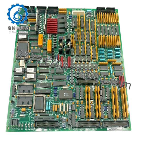
| Model Number | DS200TCQAG1B |
| Series | Mark V Speedtronic |
| Functional Description | RST Analog I/O Board |
| Functional Acronym | TCQA |
| Product Type | Analog I/O Board |
| Main Connectors | 4 × 34-pin connectors |
| Additional Connectors | 2 × 40-pin connectors |
| Jumper Count | 6 configurable jumpers |
| Indicator LEDs | 6 status LEDs |
| Supported Signals | 4–20 mA, thermocouple, LVDT, vibration, pulse, voltage |
| Application | Gas and steam turbine control systems |
| Mounting Type | Rack-mounted PCB |
| PCB Coating Style | Normal industrial coating |
| Operating Voltage | 24 V DC control environment |
| Operating Temperature | 0 °C to 60 °C |
| Storage Temperature | −40 °C to +85 °C |
| Humidity Rating | 5% to 95% non-condensing |
| Approximate Weight | 0.6–0.8 kg |
| Warranty | 12 Months |
4. Product Introduction
The GE DS200TCQAG1B is an RST Analog I/O Board used in GE Mark V Speedtronic turbine control systems. The board scales, conditions, and processes analog signals from terminal boards installed on the R1, R2, and R3 I/O cores, including thermocouple, LVDT, vibration, pulse, and 4–20 mA process signals.
In operating turbine plants, this board is commonly retained during lifecycle extension projects because replacing the complete Mark V architecture introduces significant commissioning and validation work. Engineers typically match the exact DS200TCQAG1B revision to avoid analog scaling inconsistencies and communication faults after startup.
5. Installation & Configuration Guide
Stage 1: Pre-Installation Preparation (Estimated Time: 10 Minutes)
⚠️ Safety First
- Notify operations before shutdown.
- Verify turbine systems are in a safe maintenance condition.
- Apply lock out/tag out procedures.
- Disconnect cabinet power and wait at least 5 minutes for discharge.
⚠️ Mark V cabinets can retain residual voltage after shutdown. Verify the DC rail with a meter before touching the rack.
Tools Required
- ESD wrist strap
- PH1 screwdriver
- Fluke 115 multimeter
- Wire labels
- Smartphone for reference photos
- Flashlight for cabinet inspection
Data Backup
- Export current Mark V configuration data.
- Photograph all ribbon cable and terminal connections.
- Record jumper positions:
- J1
- J2
- J5
- J6
- J7
- J8
- Document cabinet slot location and associated terminal boards.
❗ This step gets skipped constantly during outage pressure. Then somebody spends half a shift trying to remember where the JG connector was routed.
Stage 2: Removing the Old Module (Estimated Time: 5–10 Minutes)
- Remove the cabinet access cover.
- Label all ribbon cables and field connectors.
- Disconnect cables carefully without twisting connectors.
- Remove retaining screws and washers.
- Pull the board straight outward.
⚠️ Do not rock the PCB side to side. Older Mark V rack connectors are fragile, and bent pins cause intermittent analog faults that are miserable to troubleshoot.
- Inspect:
- Backplane connectors
- Ribbon cables
- Edge contacts
- Dust buildup
- Heat discoloration
- Corrosion around terminals
Field Reminder
Keep the original board beside the cabinet until commissioning is complete. I’ve seen technicians throw away old hardware too early, then realize they needed jumper references from the original card.
Stage 3: Installing the New Module (Estimated Time: 10 Minutes)
- Wear a grounded ESD strap before opening the anti-static packaging.
- Verify the exact part number:
- DS200TCQAG1B
- Confirm connector layout and revision markings match the removed board.
Configuration Clone (Crucial)
- Replicate all jumper settings exactly.
- Verify current range jumper positions for the mA output circuits.
- Confirm ribbon cable orientation.
- Check shielding and grounding practices.
❗ This is the most common rookie mistake in Mark V cabinets. One incorrect jumper position can create unstable analog scaling or false vibration readings throughout the system.
- Insert the board evenly into rack guides.
- Ensure the board seats fully.
- Tighten retaining screws evenly.
- Reconnect all connectors carefully.
Self-Checklist
- Model verified
- Jumpers copied correctly
- Ribbon cables secure
- Grounding verified
- Board fully seated
Stage 4: Power-On & Testing (Estimated Time: 15 Minutes)
Pre-Power Check
- Verify no shorts exist on the 24 V DC rail.
- Check cabinet grounding continuity.
- Inspect all connectors and ribbon cable seating.
Power-On Steps
- Energize the control rack only.
- Observe startup LEDs.
- Verify communication with the Mark V controller.
- Confirm analog values appear correctly in diagnostics.
- Perform dry-run I/O simulation before returning field devices to service.
⚠️ If analog readings suddenly peg high or low after startup, stop immediately and verify jumper configuration and cable orientation before replacing additional hardware.
SOP Testing Performed Before Shipment
Each DS200TCQAG1B unit undergoes:
- Inbound Inspection & Traceability
- OEM label verification
- Serial number inspection
- Connector and solder inspection
- Anti-counterfeit visual checks
- Live Functional Testing
- Tested on a genuine GE Mark V rack
- Analog signal simulation
- Communication handshake verification
- Continuous load testing exceeding 24 hours
- Electrical Parameter Testing
- 500 V insulation resistance test (>10 MΩ)
- Ground continuity verification
- Power rail stability testing
- Firmware & Configuration Verification
- Jumper documentation
- Connector verification
- Revision inspection and photographic records
- Final QC & Packaging
- Anti-static ESD bagging
- Bubble wrap and reinforced export carton
- QC inspection sign-off with test date
Test videos and inspection photos are available upon request.

- DS200TCQAG1B
- DS200TCQAG1B
6. Frequently Asked Questions (FAQ)
Q1: Can the DS200TCQAG1B be hot-swapped?
No.
The Mark V platform was not designed for routine hot-swapping of analog boards. Pulling this board live can damage the backplane or create unstable analog references throughout the turbine control system.
Shut the cabinet down properly first.
Q2: Is the DS200TCQAG1B obsolete?
Yes. The Mark V platform is legacy equipment and no longer in active OEM production. Most available inventory today comes from surplus industrial stock or tested refurbishment channels.
Many plants continue operating Mark V systems because a full migration project requires major outage coordination, FAT/SAT testing, and logic validation.
Q3: What signals does this board process?
The DS200TCQAG1B handles multiple analog and process-related signals including:
- 4–20 mA inputs and outputs
- Thermocouple signals
- LVDT position feedback
- Vibration monitoring
- Pulse inputs
- Generator and line voltage signals
The board scales and conditions these signals before passing them deeper into the Mark V architecture.
Q4: Is this genuinely new hardware?
This listing refers to New Original / New Surplus inventory unless otherwise labeled.
That generally means:
- No previous field installation
- OEM-manufactured hardware
- Long-term industrial spare storage
Because these boards are older, outer packaging may show storage wear. Every board is inspected for oxidation, damaged traces, and connector deterioration before shipment.
Q5: What causes the most startup problems after replacement?
Incorrect jumper replication and ribbon cable orientation.
I’ve seen engineers install the board correctly mechanically but reverse a ribbon cable during a rushed outage. The cabinet powered up, but analog readings drifted all over the place for hours before the issue was found.
Take photos before disconnecting anything.
Q6: Will replacing this board erase turbine logic?
Normally no. The DS200TCQAG1B primarily handles analog I/O conditioning rather than storing primary sequencing logic.
Still, always back up the system before maintenance. I’ve seen undocumented analog scaling adjustments disappear because nobody exported the configuration first.
Q7: Why are surplus Mark V boards still expensive?
Because outage costs are usually much higher than hardware costs.
A turbine outage waiting on one analog I/O board can cost far more in lost generation revenue than the board itself. That keeps demand high for verified spare inventory with documented testing.
❗ I once watched a technician handle a replacement board during winter maintenance without an ESD strap. The cabinet powered up for less than five seconds before the board failed permanently. That mistake extended the outage another full shift.
Keep these checks in mind and you’ll save yourself 90% of typical rework time.


