
 WhatsApp: +86 16626708626
 Email:
  Phone: +86 16626708626
Description
3. Key Technical Specifications
| Parameter | Value |
| System Compatibility | Mark V Speedtronic (Core , , , and ) |
| Input Voltage | 125 VDC (Nominal) |
| Output Voltages | Regulated +/- 15 VDC, 5 VDC, 24 VDC |
| Board Acronym | UPSA |
| Fuse Protection | On-board pluggable fuses for output rails |
| Connection Points | J1 through J10 Screw Terminals and Pin Headers |
| Mounting | Standoff mount within the power distribution frame |
| Indicators | Diagnostic LEDs for input/output status |
4. Product Introduction & Supply Chain Strategy
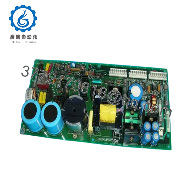
The GE DS200UPSAG1ADB is a critical power management component within the Mark V Speedtronic control system. It is designed to bridge the gap between the primary power source and the sensitive processor boards, ensuring that voltage spikes or momentary drops do not crash the turbine control logic. It filters and regulates the 125 VDC station battery power into the various isolated voltages required by the rack modules.
From a TCO (Total Cost of Ownership) perspective, the UPSA board is one of the most vital spares to hold in New Surplus condition. Power supply boards are prone to “dry” electrolytic capacitors and heat-related degradation over decades of service. Replacing a failing power board with a New Surplus unit, rather than a repaired one, eliminates the risk of “dirty” power ripple which can cause phantom faults and intermittent processor resets—issues that are notoriously difficult and expensive to troubleshoot.
5. Installation & Configuration Guide
Stage 1: Pre-Installation (Prep & Safety)
Power down the specific control core being serviced and isolate the 125 VDC input. Use a DMM (Digital Multimeter) to verify zero voltage at the input terminals. Put on an ESD wrist strap. Document the wire positions on the terminal blocks and take note of the fuse ratings currently installed on the old board.
Stage 2: Removal
Carefully unscrew the wiring from the terminal blocks J1-J10. Remove the mounting screws or nylon standoffs securing the board to the chassis. Lift the board out, being careful not to snag any of the adjacent wiring harnesses.
Stage 3: Installation (Clone & Seat)
Inspect the new DS200UPSAG1ADB to ensure all on-board fuses are seated and match the amperage of the original board. Mount the board onto the standoffs. Reconnect the wiring to the terminal blocks, ensuring every screw is torqued correctly to prevent high-resistance connections.
Stage 4: Power-On & Testing
Apply 125 VDC input power. Check the on-board diagnostic LEDs; all output rail LEDs should be green. Measure the output test points with a multimeter to verify +5 VDC, +15 VDC, and -15 VDC levels are within 2% of nominal before connecting the ribbon cables to the downstream processor boards.
6. Firmware/Software Versions & Upgrade Notes
- Hardware Revisions: The ‘ADB’ suffix denotes a specific revision level. While generally interchangeable with ‘ADA’ versions, always verify that the physical layout of terminal blocks matches your cabinet’s wiring harness.
- No Software Required: As a hardware-level power distribution board, the DS200UPSAG1ADB does not require firmware loading or software configuration. It is a “plug-and-play” power component.
- Legacy Risk: Do not mix-and-match fuses from different board revisions. Use only the fuse values specified on the PCB silkscreen of the new board.

- DS200UPSAG1ADB
7. Frequently Asked Questions (FAQ)
Does this board include the fuses?
Yes, our New Surplus DS200UPSAG1ADB units typically ship with the standard factory fuse set installed. We recommend verifying these ratings against your specific site manual before energizing.
Why shouldn’t I just buy a refurbished UPSA board?
Power boards are high-stress components. Refurbished units have likely undergone thousands of thermal cycles, drying out the capacitors. A New Surplus board provides a “fresh clock” on these life-limited components, ensuring another 10-15 years of reliable service.
Can this board handle 110 VAC input?
No. This specific version is designed for 125 VDC input, typically sourced from a station battery bank or a DC power bus. Applying AC power will result in immediate board failure and potential fire hazards.
What causes these boards to fail most often?
The most common failure points are blown fuses due to downstream shorts or capacitor failure caused by high ambient temperatures within the control cabinet.
Are the terminal blocks included?
The screw terminals are integrated directly onto the PCB. You will simply need to land your existing field wiring into the new terminals.


