
 WhatsApp: +86 16626708626
 Email:
  Phone: +86 16626708626
Description
3. Key Technical Specifications
| Parameter | Value |
|---|---|
| Manufacturer | GE General Electric |
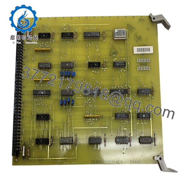
| Model | DS3800HADA1A1A |
| Product Type | Printed Circuit Board / Address Decoder Board |
| Series | GE Mark IV DS3800 |
| Functional Purpose | Signal decoding and routing |
| Configuration Method | 8 onboard jumpers |
| Signal Device | Decoder/Demultiplexer |
| Connector Type | Wire-wrap pin interface |
| Installation Type | Mark IV rack insertion |
| PCB Construction | Industrial multi-layer board |
| Configuration Method | Hardware jumper selection |
| Firmware Device | None documented |
| Approximate Weight | 0.5–0.9 kg |
| Application | Gas and steam turbine control systems |
The DS3800HADA1A1A board contains an onboard decoder/demultiplexer and eight configurable jumpers used for field setup and signal routing inside GE Mark IV turbine control systems.
4. Product Introduction
GE DS3800HADA1A1A is a Mark IV printed circuit board used in GE Speedtronic turbine control systems. The board performs address decoding and signal routing tasks required by Mark IV control architecture and uses configurable jumpers for hardware setup.
In field deployments of Mark IV systems, boards like this commonly remain installed for decades. Plants running legacy gas turbines frequently keep spares because replacing a single board during an outage is usually faster and lower risk than redesigning a complete controls platform. The onboard decoder/demultiplexer processes multiple signals and combines routing paths within the control structure.
- DS3800HADA1A1A
5. Installation & Configuration Guide
Stage 1: Pre-Installation Preparation
Estimated Time: 10 minutes
⚠️ Safety First: Notify operations personnel of planned downtime. Verify safe process state. Apply lockout/tagout procedures. Wait at least 5 minutes for stored energy discharge.
Tools Required
- ESD wrist strap
- PH1 screwdriver
- Fluke 115 multimeter
- Wire labels
- Smartphone for photos
Data Backup
- Record cabinet location and slot position.
- Photograph all wiring and connector orientation.
- Take clear pictures of all eight jumpers.
- Record board suffix and revision details.
- Label all cables before touching anything.
Stage 2: Removing the Old Module
Estimated Time: 5 minutes
- Remove cabinet access cover.
- Label field and backplane wiring.
- Disconnect attached cables carefully.
- Release retention hardware.
- Pull board straight outward.
- Inspect rack pins and edge contacts.
⚠️ Keep the old board available until startup is complete.
I’ve seen maintenance crews finish installation and then realize nobody documented jumper settings.
Stage 3: Installing the New Module
Estimated Time: 10 minutes
- Wear grounded ESD protection.
- Verify DS3800HADA1A1A matches exactly.
- Configuration Clone (Crucial): Replicate all jumper settings exactly.
- Compare old and new jumper positions side by side.
- Insert board evenly into guide rails.
- Lock board hardware.
- Reconnect all wiring.
Self-Checklist:
[ ] Jumpers match
[ ] Wiring secure
[ ] Tabs locked
[ ] Connector orientation verified
❗This is the most common rookie mistake, but it happens constantly. Take a picture before you pull it. I can’t stress this enough.
Stage 4: Power-On & Testing
Estimated Time: 5 minutes
Pre-Power Check
Use a Fluke 115 and verify no shorts on supply rails.
Power-Up Steps
- Energize rack power only.
- Observe startup indicators.
- Verify system communication status.
- Confirm module recognition.
- Restore configuration if required.
- Dry-run functional testing.
⚠️ Troubleshooting Note: If startup faults occur immediately, suspect jumper mismatch before assuming board failure.
Veteran Survival Guide — Technical Pitfalls
❗ Firmware Revision Mismatch
This board itself does not appear to contain programmable firmware, but revision suffixes still matter.
I’ve seen maintenance teams assume “same board family” meant identical functionality. Two shifts later they discovered the revision mismatch.
Document the entire suffix.
❗ DIP Switch / Jumper Misconfiguration
The board includes 8 configuration jumpers. Factory settings may not match plant requirements.
Take photos first.
You think you’ll remember. You won’t.
❗ Terminal and Connector Assumptions
Even within GE Mark IV hardware families, connector assignments and pin definitions can change.
Do not wire from memory.
Always verify documentation.
❗ Power Consumption Oversight
Calculate rack loading and leave a minimum 20% power margin.
Aging Mark IV power supplies already operate closer to their limits than most people realize.
❗ ESD Damage
I once watched an engineer handle a replacement board in dry winter conditions without grounding. Powered it up and immediately released smoke.
That was a costly lesson.
Keep these checks in mind and you’ll save yourself 90% of typical rework time.
SOP Quality Transparency
1. Inbound Inspection & Traceability
- Verify OEM packing documentation and sourcing records
- Check serial labels and anti-counterfeit identifiers
- Inspect PCB surfaces for corrosion, scratches, UV yellowing, and repair evidence
- Verify included accessories and paperwork
2. Live Functional Testing
Testing performed using genuine GE Mark IV hardware where available.
Procedure:
- Power-on self-test
- Startup verification
- Signal path verification
- Jumper validation
- Communication checks
- Continuous operation exceeding 24 hours with thermal monitoring
- Generate documented test report
Test photos and startup videos available upon request.
3. Electrical Parameter Testing
- 500 V Megger insulation resistance test (>10 MΩ)
- Ground continuity verification
- Fluke 115 voltage measurements
- Hipot testing where applicable
4. Firmware & Configuration Verification
- Document hardware revision
- Record jumper positions
- Photograph board configuration
5. Final QC & Packaging
- QC sign-off
- Anti-static ESD packaging
- Bubble wrap protection
- Heavy-duty corrugated carton
- QC-passed label with inspection date
Verified fully functional under load testing.
6. Frequently Asked Questions (FAQ)
Q1: Can I hot-swap this module?
No.
Mark IV hardware was never designed around live insertion. Pulling boards under power risks backplane damage and unpredictable faults.
Power down first.
Q2: Is DS3800HADA1A1A obsolete?
Yes.
The board belongs to GE’s legacy Mark IV turbine platform. Current inventory usually comes from surplus channels or specialized industrial suppliers.
Q3: Is this genuinely new hardware?
Most current inventory is New Surplus or tested refurbished stock rather than recent factory production. Available market listings vary significantly by condition and packaging.
Q4: What is the most important installation checkpoint?
Jumpers.
I’ve seen maintenance teams troubleshoot cabinets for six hours only to discover one incorrect jumper position. The board uses jumper-based configuration and replacement boards should mirror the original setup exactly.
Q5: Why is your price lower than OEM list pricing?
Most inventory comes from decommissioned plants, surplus procurement stock, and canceled projects rather than active OEM production.
Q6: Is DS3800HADA1A1A a processor board?
No.
Available documentation identifies it as a printed circuit board using decoder/demultiplexer circuitry rather than a primary controller processor.
Q7: Are test reports available before shipment?
Yes.
Request startup photos, runtime logs, and verification reports before shipment. That documentation usually prevents avoidable startup surprises.


