
 WhatsApp: +86 16626708626
 Email:
  Phone: +86 16626708626
Description
3. Key Technical Specifications
| Parameter | Value |
|---|---|
| Manufacturer | General Electric |
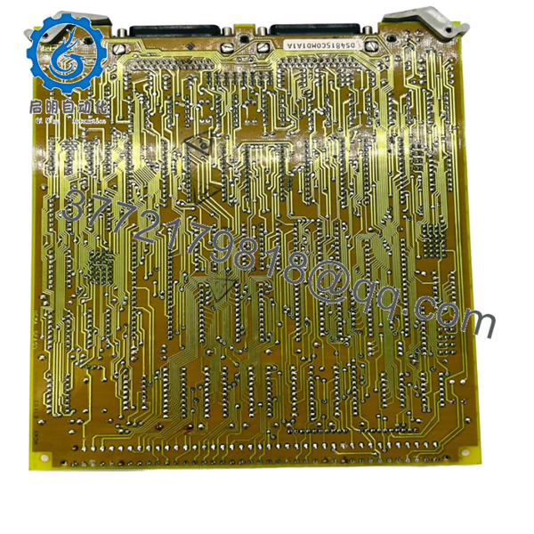
| Model Number | DS3800HCMA1E1G |
| Product Series | Speedtronic Mark IV DS3800 |
| Board Type | Dual Communications Control Board |
| Application | Turbine and drive communication control |
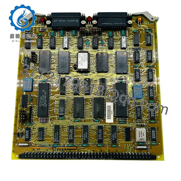
| Connector Configuration | Dual 34-pin communication connectors |
| Jumper Count | 20 configurable jumpers |
| LED Indicators | 1 amber LED, 2 red LEDs |
| Mounting Method | Rack-mounted PCB with retention levers |
| Interface Style | Modular drive connector |
| PCB Coating | Standard industrial conformal coating |
| System Compatibility | GE Mark IV turbine control cabinets |
| Diagnostic Features | Onboard LEDs and test points |
| Approximate Weight | 0.4–0.7 kg |
| Handling Requirement | ESD-safe handling mandatory |
| Functional Revision | E-rated and G-rated revisions referenced |
The DS3800HCMA1E1G is designed as a dual communications interface board for GE Mark IV turbine control systems. It manages communication paths between control subsystems and associated drive hardware. Verify exact revision compatibility before installation.
4. Product Introduction
The GE DS3800HCMA1E1G is a Dual Communications Control Board used within GE Speedtronic Mark IV turbine control systems. The board manages communication traffic between turbine control subsystems, interface cards, and associated drive hardware.
In field deployments of older Mark IV systems, this board is still commonly maintained as a critical spare because communication faults can force a turbine startup inhibit or trigger nuisance trips. Engineers usually replace the board directly during outages instead of attempting a full controls migration under tight downtime constraints.

- DS3800HCMA1E1G
- DS3800HCMA1E1G
5. Installation & Configuration Guide
Stage 1: Pre-Installation Preparation (Estimated Time: 10–15 Minutes)
⚠️ Safety First
- Notify operations before shutdown.
- Verify turbine safe state.
- Apply lock out/tag out procedures.
- Wait at least 5 minutes for capacitor discharge.
- Verify zero voltage using a calibrated Fluke 115 multimeter.
Older Mark IV cabinets sometimes retain residual charge longer than expected, especially around power supply sections.
Tools Required
- Grounded ESD wrist strap
- PH1 screwdriver
- Fluke 115 multimeter
- Wire labels
- Smartphone for documentation photos
- ESD-safe mat
- Flashlight for cabinet inspection
Data Backup
- Export turbine and communication configuration data where possible.
- Record cabinet slot location.
- Photograph:
- Jumper positions
- Ribbon cable orientation
- Connector routing
- Grounding straps
- Label every cable before removal.
⚠️ I’ve seen experienced technicians assume they could “remember the jumper layout.” Three hours later they were tracing communications faults channel by channel.
Stage 2: Removing the Old Module (Estimated Time: 5–10 Minutes)
- Remove the cabinet protective cover.
- Label and disconnect all ribbon and communication connectors.
- Release retention levers carefully.
- Remove mounting hardware if applicable.
- Pull the board straight outward to avoid connector damage.
- Inspect:
- Bent pins
- Oxidation
- Dust buildup
- Heat discoloration
- Cracked solder joints
⚠️ Important: Keep the original board available until the replacement passes runtime testing.
I’ve watched maintenance crews discard an old board immediately, only to discover the replacement revision had different jumper defaults and incompatible communication behavior.
Stage 3: Installing the New Module (Estimated Time: 10 Minutes)
- Wear the grounded ESD strap before touching the board.
- Verify exact model:
- DS3800HCMA1E1G
- Confirm revision markings match the original hardware where possible.
Configuration Clone (Crucial)
Replicate:
- All 20 jumper positions
- Connector orientation
- Shield grounding configuration
- Communication addressing settings
⚠️ This is one of the most common startup failure points in Mark IV systems. One incorrect jumper can create intermittent communication alarms that only appear during turbine startup.
- Insert the board evenly into rack guides.
- Lock retention levers fully.
- Reconnect all cables carefully.
Self-Checklist
- Model numbers match
- Jumpers duplicated correctly
- Connectors fully seated
- Retention levers locked
- Grounding verified
- No loose hardware inside cabinet
Stage 4: Power-On & Testing (Estimated Time: 15–20 Minutes)
Pre-Power Check
- Verify no short exists on the 24 V control rail.
- Confirm cabinet grounding continuity.
- Inspect all communication connectors.
Power-On Sequence
- Energize the control rack first.
- Observe LED behavior:
- Amber LED indicates alert state
- Red LEDs indicate fault conditions
- Verify communication initialization.
- Connect engineering workstation if available.
- Confirm communication handshakes with associated subsystems.
- Perform dry-run communication tests before enabling field operation.
Functional Verification
Check:
- Stable communication traffic
- No watchdog alarms
- No communication timeout faults
- Proper LED status indication
The onboard LEDs provide immediate diagnostic feedback during startup and troubleshooting.
⚠️ Troubleshooting Note
If communication faults appear after installation:
- First suspect jumper mismatch.
- Second inspect connector seating.
- Third verify board revision compatibility.
I once saw a plant lose nearly an entire night shift because a replacement board had slightly different communication timing behavior than the original revision. Hardware looked identical. Startup diagnostics kept throwing intermittent communication timeout alarms.
Technical Pitfall & Survival Guide
❗ Firmware and Revision Mismatch
Different DS3800HCMA revisions may behave differently under load.
Avoidance:
Document the complete suffix and revision markings before ordering.
I’ve seen communication instability caused by subtle timing differences between revisions.
❗ Jumper Misconfiguration
This board uses 20 jumpers to configure communication behavior.
Avoidance:
Photograph every jumper before removal. Duplicate settings exactly.
Do not rely on factory defaults.
❗ Connector Seating Problems
The dual 34-pin connectors must seat evenly.
Avoidance:
Insert the board straight into the rack and confirm retention levers lock properly.
A partially seated connector can create intermittent faults that are extremely difficult to trace.
❗ Power Supply Margin Issues
Older Mark IV cabinets often operate near PSU limits.
Avoidance:
Calculate cabinet load and maintain at least 20% current margin.
❗ Electrostatic Discharge (ESD)
These communication boards are vulnerable to static damage.
Avoidance:
Use grounded wrist straps and ESD-safe work surfaces.
I once watched a technician unpack a spare board during dry winter conditions without grounding himself. The board powered up, then immediately lost one communication channel permanently. Expensive mistake.
Keep these checks in mind and you’ll save yourself 90% of typical rework time.
6. Frequently Asked Questions (FAQ)
Q1: Can I hot-swap the DS3800HCMA1E1G?
No.
The Mark IV platform was not designed for live insertion of communication boards. Hot-swapping can corrupt communications, damage the backplane, or trigger turbine trips.
Power the cabinet down fully before replacement.
Q2: Is the DS3800HCMA1E1G obsolete?
Yes.
This board belongs to the GE Mark IV legacy platform. Most available inventory today comes from:
- New surplus stock
- Plant spare inventories
- Professionally refurbished units
Factory-sealed inventory still exists but quantities are limited globally.
Q3: What do the onboard LEDs indicate?
The board includes:
- 1 amber LED for alert conditions
- 2 red LEDs for fault indication
These indicators provide quick diagnostic visibility during startup and troubleshooting.
Q4: Will replacing this board erase turbine logic?
Usually no.
The DS3800HCMA1E1G does not normally contain the primary turbine application logic. That logic typically resides in the main Mark IV processors.
However, jumper settings and communication configuration still matter greatly.
Q5: Why are some surplus units priced much lower than others?
Usually because of:
- Unknown testing status
- Missing traceability
- Cosmetic damage
- Refurbished boards sold unclearly
Always request:
- Serial photos
- QC reports
- Runtime test verification
- Packaging photos
- Connector close-up photos
A serious supplier should provide all of them without hesitation.
Q6: What should I verify before ordering?
At minimum verify:
- Exact model number
- Full suffix revision
- Jumper configuration
- Connector compatibility
- Cabinet slot assignment
- Existing Mark IV revision level
Even visually identical DS3800 communication boards may not be electrically interchangeable.
Q7: What quality testing should a supplier perform before shipment?
Minimum acceptable QC should include:
- Visual PCB inspection
- Connector integrity inspection
- LED startup verification
- Insulation resistance testing (>10 MΩ preferred)
- Communication handshake testing
- 24-hour powered runtime testing
- ESD-safe packaging and sealing
Good suppliers should also provide:
- Test videos
- QC photos
- Runtime verification reports
- Packaging photos before shipment
A board tested on a genuine Mark IV rack is substantially more meaningful than a simple “power-on tested” label.


