
 WhatsApp: +86 16626708626
 Email:
  Phone: +86 16626708626
Description
3. Key Technical Specifications
| Parameter | Value |
|---|---|
| Model | DS3800HCMC1A1B |
| Brand | GE (General Electric) |
| Series | Mark IV Speedtronic |
| Board Type | High Speed Counter / Pulse Accumulator |
| Power Supply | +5V DC from backplane |
| Current Draw | 0.6A typical on +5V rail |
| Counter Channels | 4 independent |
| Input Frequency | 0 to 50 kHz per channel |
| Input Types | TTL (0-5V), magnetic pickup (MPU), or contact closure |
| Input Impedance | 10k ohms (TTL), 1k ohms (MPU) |
| MPU Sensitivity | 100 mV peak-to-peak minimum |
| Count Modes | Up/down, quadrature, direction discrimination |
| Counter Width | 16-bit or 32-bit (configurable) |
| Latch Inputs | 4 (one per channel, hardware latch) |
| Preset Inputs | 4 (one per channel, hardware preset) |
| Outputs | 4 x TTL (programmable limit switches) |
| Update Rate | 1 ms (16-bit mode), 2 ms (32-bit mode) |
| Accuracy | ±1 count (no accumulated error) |
| Isolation | Optical isolation on inputs (500V DC) |
| Status LEDs | 8 x LEDs (Counter 1-4 Active, Latch 1-4 Active) |
| DIP Switches | 8-position (input type, count mode, output configuration) |
| Operating Temp | 0 to +50°C (32 to 122°F) |
| Storage Temp | -40 to +85°C (-40 to 185°F) |
| Dimensions | 9.5 x 6.5 x 1.0 inches (approx) |
| Connectors | 1 x 96-pin backplane, 1 x 37-pin D-sub (field I/O) |
| GE Part Family | DS3800 (Mark IV) |
4. Product Introduction
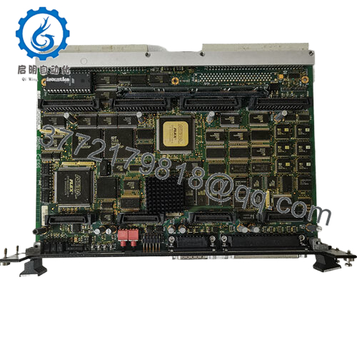
The GE DS3800HCMC1A1B is the HCMC high-speed counter module for the Mark IV Speedtronic turbine control system. This board counts high-frequency pulse trains from speed sensors, flow meters, tachometers, and position encoders in gas and steam turbine applications. You’ll find it in overspeed detection, shaft speed measurement, flow totalization, and actuator position feedback systems.
The HCMC board provides four independent counter channels. Each channel accepts TTL, magnetic pickup (MPU), or contact closure inputs at frequencies up to 50 kHz. The board supports up/down counting, quadrature decoding (for incremental encoders), and direction discrimination. Each channel has a hardware latch input for snapshot capture and a programmable limit switch output. The Mark IV main processor reads the accumulated counts over the VME backplane at 1-2 ms intervals. If your turbine speed readings are erratic, missing pulses, or not updating, this board is the direct interface between the field sensors and the control logic.
5. Installation & Configuration Guide
Estimated time for replacement by a qualified technician: 35 minutes
Stage 1: Pre-Installation Preparation (10 minutes)
⚠️ Safety First: Notify operations of turbine shutdown. Verify the steam supply is locked out and the turbine is at rest (0 rpm). Lock out/tag out control power to the Mark IV rack. Wait 5 minutes for capacitors to discharge.
Tools Required:
- ESD wrist strap (grounded to earth)
- Small flathead screwdriver (for DIP switches)
- Signal generator (for bench test) or known-good pulse source
- Multimeter with frequency measurement capability
- Smartphone for photos
- Small needle-nose pliers (for jumpers)
Data Backup & Documentation:
- Take a high-resolution photo of the 8-position DIP switch bank. Record every position.
- Photograph any jumpers on the board (input type select, pull-up resistors).
- Document which counter channel connects to which field device (e.g., Channel 1 = Turbine speed probe A).
- Record the current count mode for each channel (up/down, quadrature, etc.) from the Mark IV configuration.
- Note the preset and latch wiring connections (if used).
Stage 2: Removing the Old Module (10 minutes)
Step 1: Remove the 37-pin D-sub connector (field wiring). Loosen the two jackscrews completely. Do not pull on the cable.
Step 2: Label the connector if not already marked. Use permanent wire labels.
Step 3: Release the board ejectors (top and bottom). Pull the board straight out of the backplane. No rocking — this bends backplane pins.
Step 4: Inspect the backplane connector for bent pins, corrosion, or debris. Use a flashlight.
Step 5: Place the old board on an ESD mat. Keep it as a reference until the new board is running.
Stage 3: Installing the New Module (15 minutes)
Step 1 (ESD): Ground your wrist strap. Unpack the new DS3800HCMC1A1B on an ESD mat.
Step 2 (Verify Model): Confirm the new board label reads DS3800HCMC1A1B exactly. Different suffixes (e.g., 1A1A vs 1A1B) may have different input threshold voltages.
Step 3 (Clone Configuration — Critical):
- Set all 8 DIP switches exactly as photographed.
- Set any jumpers to match the old board (input type, pull-up resistor enable).
- Pay special attention to switch settings for input type (TTL vs MPU) — wrong setting can damage the input circuit.
Step 4: Insert the board into the same backplane slot. Push evenly until both ejectors latch. Listen for the click.
Step 5: Reconnect the 37-pin D-sub connector. Tighten jackscrews finger-tight plus 1/4 turn. Do not overtighten.
Self-Checklist:
- DIP switches match old board exactly
- Jumpers verified
- Board fully seated (ejectors locked)
- 37-pin connector secured
Stage 4: Power-On & Testing (10 minutes)
Pre-Power Check:
With power off, measure resistance between each input pin and ground. Should be >10k ohms. Below 1k ohm indicates a shorted sensor or cable.
Power-On Steps:
- Apply power to the Mark IV rack.
- Observe the status LEDs on the HCMC board:
- Power LED (green): Must be on.
- Channel Active LEDs (4): Will blink when pulses are present.
- Latch Active LEDs (4): Illuminated when latch input is active.
- Connect the maintenance terminal. Navigate to the counter status screen.
- For each channel, verify the count value is stable and reasonable (0 rpm at standstill).
- Pulse injection test: Use a signal generator to inject a known frequency (e.g., 1 kHz square wave, 5V TTL) into Channel 1.
- In the maintenance terminal, verify the count increments at 1000 counts per second.
- If using quadrature mode, inject two phase-shifted signals and verify direction detection.
- Latch test: Toggle the latch input for Channel 1. Verify the count value is captured and held.
- Preset test: Toggle the preset input. Verify the counter resets to the preset value.
- Verify the Mark IV control logic reads the counters correctly. Check speed display, totalized flow, or position feedback.
⚠️ Troubleshooting:
| Symptom | Likely Cause | Action |
|---|---|---|
| Channel LED off, no count | Input signal missing or wrong input type | Measure input voltage with oscilloscope. Verify DIP switch setting (TTL vs MPU). |
| Count jumps or misses pulses | Input signal too slow rise time or electrical noise | Use shielded twisted pair cable. Add a Schmitt trigger in the field if needed. |
| Count increments when it should decrement | Direction logic reversed (quadrature mode) | Swap A/B signals on the encoder. Reverse direction in configuration. |
| Latch does not capture count | Latch input not wired or wrong polarity | Toggle latch input manually. Measure voltage at terminal. Verify polarity in DIP switches. |
| Counter resets randomly | Preset input floating or electrical noise | Add a pull-up resistor on the preset input (10k ohm to +5V). |
| All channels read zero | Backplane communication failure or board fault | Check board LEDs. Reseat board. Replace if fault persists. |
| Count value is half of expected | Wrong count mode (quadrature x1 vs x4) | Change configuration in Mark IV software. Check encoder resolution. |

- DS3800HCMC1A1B
6. Frequently Asked Questions (FAQ)
Q: Is the DS3800HCMC1A1B a direct replacement for older HCMC boards like HCMC1A or HCMC1A1A?
A: Yes, with verification of input voltage thresholds. The “1A1B” suffix indicates a specific revision. It is backward compatible with earlier HCMC boards. However, the input threshold for MPU signals may differ slightly (100 mV vs 150 mV). If your magnetic pickup produces a very low amplitude signal (e.g., <200 mV at minimum speed), the new board may not see it. Test with a known-good signal generator before commissioning. We can verify sensitivity on our test stand.
Q: Can I use this board to measure turbine speed from a magnetic pickup (MPU)?
A: Yes, with conditions. The HCMC accepts MPU inputs (two-wire, no external power). The MPU generates a sine wave proportional to speed. Minimum amplitude for reliable counting is 100 mV peak-to-peak. At very low speeds (e.g., turning gear at 10 rpm), the MPU output may drop below 100 mV. In this case, use a speed converter (e.g., GE HSS module) to amplify the signal before feeding it to the HCMC.
Q: What is the maximum input frequency for the HCMC?
A: 50 kHz per channel in 16-bit mode. At 50 kHz, the counter rolls over every 1.31 seconds in 16-bit mode (65535 counts). For high-speed applications (e.g., 60,000 rpm = 1 kHz for a 1-pulse-per-rev sensor), this is fine. For higher frequencies or longer accumulation periods, use 32-bit mode (rollover every 86 seconds at 50 kHz). Set the mode in the Mark IV configuration.
Q: Can I hot-swap the HCMC board while the turbine is running?
A: No. The Mark IV backplane has live +5V power and communication signals. Hot-swapping can damage the backplane transceivers and corrupt data on the VME bus. Procedure: Shut down the turbine, lock out control power, wait 30 seconds, then swap. After replacement, verify all counter values before restarting.
Q: Why does my quadrature encoder count only half the expected pulses?
A: You are likely in quadrature x1 mode when you need x4 mode. Quadrature encoders produce two signals (A and B) 90° out of phase. In x1 mode, the counter increments only on one edge of one channel. In x4 mode, it increments on both edges of both channels (4 counts per cycle). Check your Mark IV configuration for the “Quadrature Multiplier” setting. Change from x1 to x4. Alternatively, your encoder may have a different resolution than expected.
Q: How do I wire a TTL pulse source to the HCMC?
A: For TTL (0-5V) signals:
- Connect signal+ to the channel’s input pin (refer to the 37-pin pinout diagram).
- Connect signal ground to the HCMC’s common ground (pin 20 or similar).
- Set the DIP switch for that channel to “TTL” mode (not MPU).
- Do not exceed 5.5V on the input — higher voltage will damage the board.
For open-collector TTL outputs (e.g., from a flow meter), you need an external pull-up resistor (2.2k ohm to +5V). We can provide a wiring diagram.
Q: What is the purpose of the Latch and Preset inputs?
A: The HCMC has hardware inputs for precise event timing:
- Latch: When the latch input is triggered (rising edge), the current count value is frozen and stored. The Mark IV can read the latched value without stopping counting. Use this for speed measurement over a fixed time interval.
- Preset: When the preset input is triggered, the counter is reset to a predefined value (usually zero or a starting offset). Use this for position homing or batch totalization.
Both inputs have optical isolation and can be driven by 24V DC field contacts or 5V TTL signals (jumper selectable).
Q: My HCMC board shows a count but the Mark IV logic doesn’t see it. What’s wrong?
A: The HCMC communicates with the main processor over the VME backplane. If the processor doesn’t see the count, suspect:
- Slot address mismatch — The Mark IV configuration expects the HCMC in a specific slot. Verify the board is in the correct slot.
- Scan time too long — The processor may be scanning the board slower than the counter updates. Check the I/O scan configuration.
- Backplane failure — Reseat the board. Try a different slot (and update the configuration).
If the board LEDs show counting activity, the board is likely good. The problem is in the processor or configuration.
Q: What’s your testing process for this board?
A: We test every DS3800HCMC1A1B on a live Mark IV test rack with a programmable pulse generator and quadrature encoder simulator. Test sequence:
- Visual inspection (corrosion, burnt components, bent pins)
- Power-on test (+5V current draw, LED sequence)
- TTL input test: All 4 channels, 1 Hz to 50 kHz square wave, verify count accuracy ±0.01%
- MPU input test: 100 mV to 10V sine wave, 10 Hz to 50 kHz, verify count accuracy
- Quadrature test: Simulate A/B signals, verify x1, x2, x4 counting modes
- Latch test: Trigger latch at random intervals, verify captured value
- Preset test: Trigger preset, verify counter resets
- Output test: Programmable limit switches — verify TTL outputs toggle at setpoint
- 24-hour burn-in with continuous counting at 50 kHz
Test report with per-channel accuracy data and pulse injection photos available upon request.
Q: What’s the warranty on this obsolete board?
A: 1-year replacement warranty. Covers failure under normal operating conditions (0-50°C, correct input voltages). Does NOT cover damage from overvoltage on inputs (e.g., applying 24V to a TTL input), ESD, water ingress, or lightning strikes. We cross-ship replacements within 24 hours for confirmed defects. We also offer a 30-day compatibility guarantee — if the board does not count correctly with your specific sensors, return it for full credit.


