
 WhatsApp: +86 16626708626
 Email:
  Phone: +86 16626708626
Description
3. Key Technical Specifications
| Parameter | Value |
|---|---|
| Manufacturer | GE General Electric |
| Model Number | DS3800HFXC |
| Product Type | Communication Interface Board |
| System Series | GE Mark IV DS3800 |
| Primary Application | Speedtronic turbine control |
| Platform Generation | Mark IV |
| Interface Function | Inter-board communications |
| Optional Expansion | Daughterboard via vertical connector |
| Connector Type | Large edge connector + pin connector assembly |
| Configuration Method | Jumper switches |
| Mounting Method | Rack-installed PCB |
| Extraction Feature | Dual extractor clips |
| PCB Construction | Multi-IC design with resistor network arrays |
| Approximate Weight | ~0.45–0.9 kg depending on packaging |
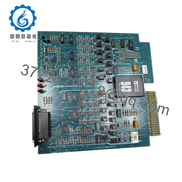
The DS3800HFXC serves as a communication interface card used in GE Mark IV Speedtronic systems and includes jumper-configurable functions with support for optional daughterboard expansion.
4. Product Introduction
GE DS3800HFXC is a communication interface board used in GE Mark IV Speedtronic turbine control systems. Its primary role is transferring communications and control signals between rack-installed boards inside gas and steam turbine environments.
In field deployments of older Mark IV systems, communication boards like DS3800HFXC become critical spares because outages rarely justify complete turbine control migrations. The board includes multiple connectors, configurable jumpers, and optional daughterboard capability for application-specific configurations.

- DS3800HFXC
- DS3800HFXC
5. Installation & Configuration Guide
Stage 1: Pre-Installation Preparation
Estimated Time: 10 minutes
⚠️ Safety First: Notify operations of planned downtime. Verify turbine safe state. Apply lockout/tagout procedures and wait at least 5 minutes for capacitor discharge.
Tools Required
- ESD wrist strap
- PH1 screwdriver
- Fluke 115 multimeter
- Wire labels
- Smartphone for photos
- Flashlight
Data Backup
- Export system configuration where available
- Record controller diagnostics
- Photograph all cable locations
- Capture jumper positions
- Photograph board labels and revision markings
❗I have seen experienced technicians skip photos because they assumed “it’s just one interface card.” Thirty minutes later they’re tracing cable positions with a flashlight.
Stage 2: Removing the Old Module
Estimated Time: 5–8 minutes
- Remove cabinet cover.
- Label every cable connection.
- Disconnect connectors carefully. Do not force terminals.
- Release extractor clips.
- Pull board straight outward.
Inspect:
- Backplane contacts
- Edge connector wear
- Dust buildup
- Bent pins
⚠️ Do not discard the original board during startup.
Leave it nearby. During troubleshooting, it often becomes the only trusted reference.
Stage 3: Installing the New Module
Estimated Time: 5 minutes
- Attach ESD strap before handling board.
- Confirm exact model: DS3800HFXC
- Configuration Clone (Crucial): Duplicate all jumper positions from the original board.
- Install evenly using board guides.
- Verify extractor clips lock fully.
- Reconnect all wiring.
Self-Checklist
- Jumpers match
- Connectors secured
- Board seated fully
- Extraction tabs locked
❗This is the most common rookie mistake, but it happens constantly. Take a picture before you pull it. I can’t stress this enough.
Stage 4: Power-On & Testing
Estimated Time: 10 minutes
Pre-Power Check
Use a Fluke 115 and verify no short exists on power rails.
Power Sequence
- Energize rack only
- Observe startup indicators
- Confirm communication status
- Connect engineering software if available
- Simulate I/O activity
⚠️ Troubleshooting Note: If communication faults appear immediately, verify jumper settings and hardware revision before replacing additional boards.
Technical Pitfall & Survival Guide
❗Firmware Revision Mismatch
Older Mark IV installations often accumulated hardware revisions over decades.
I once saw an outage continue into a second shift because a replacement board behaved differently enough to trigger communication timeouts.
Avoidance:
- Record all revision labels
- Match hardware suffixes whenever possible
- Photograph assembly tags before removal
❗DIP Switch / Jumper Misconfiguration
This board uses jumper-based configuration. Factory defaults rarely match installed systems.
Take the photo.
Then take another one.
❗Terminal Block / Connector Assumptions
Boards sharing DS3800 numbering often look nearly identical.
I’ve watched technicians reconnect cables from memory. Bad decision.
Always verify drawings.
❗Power Draw Assumptions
Calculate total rack consumption and leave 20% margin.
Small additions accumulate. Old power supplies do not tolerate surprises.
❗Electrostatic Discharge
I once watched an engineer unpack a replacement PCB during winter without a grounded strap.
Powered up once.
Never again.
Thousands of dollars disappeared in less than ten seconds.
Keep these checks in mind and you’ll save yourself 90% of typical rework time.
SOP Quality Transparency
1. Inbound Inspection & Traceability
- Verify OEM packing documents
- Review customs and traceability records
- Inspect serial labels and identification markings
- Check for scratches, corrosion, UV yellowing, and rework marks
- Audit accessories and documentation
2. Live Functional Testing
Test Environment
- Genuine GE Mark IV rack
- Simulated turbine control communications environment
Procedure
- Power-on self-test
- LED verification
- Communication handshake testing
- I/O simulation
- Continuous operation >24 hr with thermal monitoring
- Test report generation
Photos and startup videos available upon request.
3. Electrical Parameter Testing
- 500 V Megger insulation test (>10 MΩ)
- Ground continuity verification
- Hipot testing when applicable
4. Firmware & Configuration Verification
- Record hardware revision
- Document jumper positions
- Photograph labels and optional daughterboard settings
5. Final QC & Packaging
- Inspector sign-off
- Anti-static ESD bag
- Bubble protection
- Heavy-duty corrugated packaging
- QC date label
Verified fully functional under load testing.
6. Frequently Asked Questions (FAQ)
Q1. Can I hot-swap the DS3800HFXC?
No.
Do not remove it while energized. Mark IV systems were not designed for live board insertion. Pulling the card under power can damage communication buses and backplane circuitry.
Power down first.
Q2. Is DS3800HFXC obsolete?
Yes.
The GE Mark IV product family has been obsolete for many years and replacement inventory now comes primarily from surplus channels and repair vendors.
Q3. Is New Surplus inventory actually unused?
Sometimes yes.
Sometimes inventory sat untouched in a warehouse for twenty years.
Request:
- Label photos
- Test reports
- Manufacturing codes
- Packaging images
Do not guess.
Q4. Does this board store application logic?
No.
The board acts as a communications interface. Application logic typically resides elsewhere in the Mark IV architecture.
Still verify your system configuration before shutdown.
Q5. Why are some prices dramatically different?
Obsolete turbine hardware behaves differently than current production inventory.
Availability, condition, and testing history drive price more than original list cost. Some suppliers also include repair support and warranty terms.
Q6. Does the board support expansion hardware?
Yes.
The PCB includes mounting points and a connector for optional daughterboard installation. Verify compatibility before installation.
Q7. What should I inspect first if communication faults continue?
Start with:
- Jumper positions
- Edge connector cleanliness
- Backplane pins
- Hardware revision matching
I’ve seen dirty edge contacts create communication failures that looked exactly like board failures.


