
 WhatsApp: +86 16626708626
 Email:
  Phone: +86 16626708626
Description
3. Key Technical Specifications
| Parameter | Value |
|---|---|
| Manufacturer | GE |
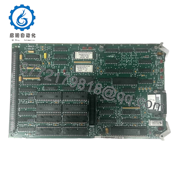
| Model | DS3800HMPJ1B1D |
| Product Family | DS3800 Series |
| System Platform | GE Mark IV Speedtronic |
| Product Type | Processor / Control PCB Module |
| Installation Method | Rack-mounted board assembly |
| Operating Voltage | System dependent via backplane |
| Communication Method | Proprietary Mark IV bus architecture |
| Firmware Dependency | Revision sensitive |
| Operating Temperature | Verify against OEM documentation |
| Board Revision | J1B1D variant |
| Condition | New Original / New Surplus |
4. Product Introduction
The GE DS3800HMPJ1B1D is an industrial control board used within GE Mark IV Speedtronic turbine control systems. It operates as part of the control architecture responsible for signal processing and system-level coordination inside legacy GE turbine platforms.
In field deployments of older Mark IV systems, replacement boards often become a maintenance issue because availability is limited and revision compatibility matters more than appearance. Many plants continue using these modules to avoid full control migrations and extended outages.
- DS3800HMPJ1B1D
5. Installation & Configuration Guide
Stage 1: Pre-Installation Preparation (Estimated: 10 minutes)
⚠️ Safety First: Notify operations of planned downtime. Confirm process shutdown status. Apply lockout/tagout procedures. Remove system power and wait 5 minutes for capacitor discharge.
Tools Required:
- ESD wrist strap
- PH1 screwdriver
- Digital multimeter
- Wire labels
- Smartphone for documentation
- Flashlight
- ESD work surface
Data Backup:
- Export available system configuration files.
- Record controller and rack information.
- Photograph all DIP switch settings.
- Photograph cable routing and terminal locations.
- Record cabinet labels and slot positions.
Stage 2: Removing the Old Module (Estimated: 5–10 minutes)
Steps:
- Remove cabinet covers and protective bezels.
- Label all field wiring and connectors.
- Disconnect cables carefully; do not pull on wiring harnesses.
- Release locking tabs.
- Pull the board straight outward.
⚠️ Note: Keep the old module nearby until startup completes successfully.
- Inspect:
- Backplane connector condition
- Bent pins
- Dust accumulation
- Corrosion
- Heat discoloration
Stage 3: Installing the New Module (Estimated: 10 minutes)
Steps:
- Attach ESD strap before touching the board.
- Verify DS3800HMPJ1B1D exactly matches the removed assembly.
- Configuration Clone (Crucial):
- Match DIP switch settings.
- Match jumpers.
- Verify addressing settings.
- Verify termination configuration.
This is the most common rookie mistake, but it happens constantly. Take a picture before you pull it. I can’t stress this enough.
- Insert module evenly.
- Push until fully seated.
- Secure mounting hardware.
- Reconnect wiring.
Self-Checklist:
- DIPs match
- Wiring secured
- Module seated fully
- Locking tabs engaged
Stage 4: Power-On & Testing (Estimated: 10–15 minutes)
Pre-Power Check:
Use a multimeter and verify no short exists on the 24 V rail.
Power sequence:
- Power rack only.
- Observe startup LEDs.
- Confirm expected boot behavior.
- Connect engineering workstation.
- Verify communication status.
- Restore configuration if required.
- Perform dry I/O testing.
LED guidance:
- Green RUN = expected operation
- Red ERR = fault condition
⚠️ Troubleshooting Note: If communication fails immediately after replacement, suspect firmware or board revision mismatch before replacing hardware again.
I’ve seen technicians replace three modules in a row while chasing a fault. The issue ended up being a revision conflict.
Technical Pitfall & Survival Guide
❗ Firmware Revision Mismatch
Issue:
A replacement board revision can behave differently than the original board.
Avoidance:
Document firmware and board revision before removal. Request matching revision ranges when ordering.
Field example:
I’ve seen projects where a technician installed a newer board and spent two days troubleshooting communication timeouts. Firmware moved from one revision branch to another and behavior changed enough to break startup.
❗ DIP Switch / Jumper Misconfiguration
Issue:
Factory defaults rarely match plant settings.
Avoidance:
Photograph every switch position.
This is the most common rookie mistake. Take a picture before you pull it.
❗ Terminal Block / Wiring Differences
Issue:
Connector layouts sometimes differ between revisions.
Warning:
Even similar modules can change pin definitions. Always verify manuals. Do not wire from memory.
❗ Power Draw Requirements
Issue:
Legacy rack power supplies often operate near capacity.
Avoidance:
Calculate total rack current and maintain a 20% margin.
Adding replacement hardware without checking power budgets creates intermittent startup faults that waste hours.
❗ Electrostatic Discharge (ESD)
Issue:
You can damage the board before installation.
Avoidance:
Wear a grounded strap and use an ESD work surface.
I once watched an engineer handle a board during dry winter conditions without protection. The module powered up once and never again. Expensive lesson.
Keep these checks in mind and you’ll save yourself 90% of typical rework time.
Quality Inspection & Functional Verification SOP
Incoming modules follow this inspection sequence:
1. Inbound Inspection & Traceability
- OEM packing verification
- Serial number validation
- Anti-counterfeit checks
- Hologram inspection where available
- Visual inspection for:
- corrosion
- scratches
- rework marks
- UV discoloration
- Accessory audit
2. Live Functional Testing
Test equipment:
- Genuine GE test rack
- Simulation environment
- Fluke 115 multimeter
Testing:
- Power-on self-test
- LED startup verification
- Communication handshake testing
- I/O simulation
- Continuous runtime testing over 24 hours
- Thermal monitoring
Official test reports available.
Test videos and photos are available upon request.
3. Electrical Testing
- Insulation resistance test:
- 500 V Megger
- Greater than 10 MΩ
- Ground continuity verification
- Hipot testing when applicable
4. Firmware Documentation
- Record firmware revisions
- Photograph DIP switches
- Record jumper positions
5. Final QC & Packaging
- QC signoff
- Anti-static ESD bagging
- Bubble protection
- Heavy-duty corrugated packaging
- QC pass labeling with inspection date
Verified fully functional under load testing.
6. Frequently Asked Questions (FAQ)
Q1: Can I hot-swap this module?
No. Do not attempt it.
The GE Mark IV platform was not designed around modern hot-swap assumptions. Removing boards under power risks backplane damage and communication faults. Kill power first.
Q2: Is GE DS3800HMPJ1B1D obsolete, and is it genuinely new?
Yes. This is an obsolete GE model with limited supply.
Most available inventory today falls into two categories:
- New Original / New Surplus
- Refurbished and tested
Always request photos of labels and actual inventory.
Q3: What is the direct replacement if stock runs out?
There is no universal drop-in replacement.
GE Mark IV systems contain revision dependencies. Verify board revision, system architecture, and OEM documentation before substituting another DS3800 assembly.
Q4: Will I lose programming when removing the board?
Usually no, but assumptions cause downtime.
Control logic often resides elsewhere within the Mark IV architecture. Still, back up all configuration information before touching hardware.
I’ve seen maintenance teams skip backups because they were “just changing a board.” That confidence disappears quickly after startup issues begin.
Q5: Why is your price lower than OEM factory pricing?
OEM support for legacy turbine controls often includes inventory carrying costs and low-volume sourcing.
New Surplus inventory generally comes from plant spare stock, canceled projects, and unused procurement inventory.
Q6: Is this module tested before shipment?
Yes.
Functional testing includes startup checks, communication verification, electrical testing, and continuous load operation before final QC release.
Test reports, photos, and videos are available upon request.
Q7: Does this include a warranty?
Typical coverage is 1 year unless otherwise specified.
Warranty covers verified operational defects under normal installation conditions. ESD damage, wiring mistakes, and field modifications are not normally covered.


