
 WhatsApp: +86 16626708626
 Email:
  Phone: +86 16626708626
Description
3. Key Technical Specifications
| Parameter | Value |
|---|---|
| Manufacturer | General Electric |
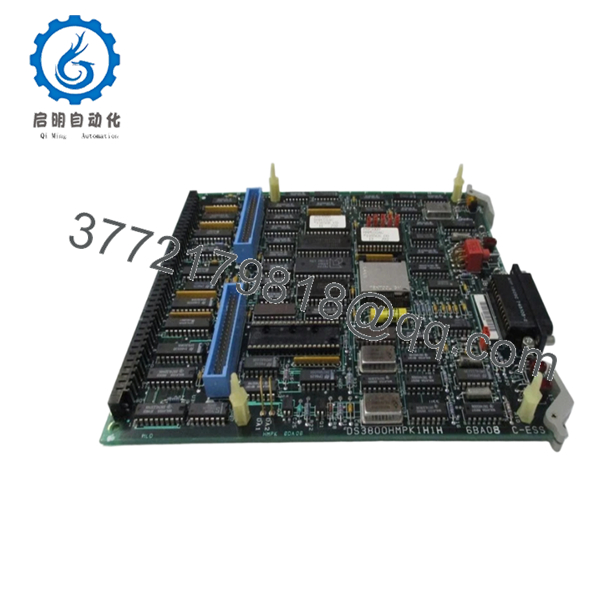
| Model | DS3800HMPK1H1H |
| Product Type | Microprocessor Board |
| Series | GE Mark IV DS3800 |
| Platform | GE Speedtronic Turbine Control |
| Firmware Storage | EPROM modules |
| Status Indicators | 3 red LEDs + 1 amber LED |
| Connector Type | One 34-pin + two 50-pin connectors |
| Mounting Method | Rack-mounted board |
| Retention Method | Locking levers |
| Typical Application | Gas and steam turbine systems |
| Product Status | Legacy / Obsolete |
| Warranty | Typically 12 months tested inventory |
The DS3800HMPK1H1H is identified as a GE Mark IV microprocessor board containing EPROM modules, multiple onboard indicators, and ribbon cable interfaces used in turbine control architectures.
4. Product Introduction
GE DS3800HMPK1H1H is a microprocessor board used within GE Mark IV Speedtronic turbine control systems. The board executes firmware instructions and coordinates board-level processing functions used in gas and steam turbine applications. It contains onboard EPROM modules, status LEDs, and multiple interface connectors.
In field deployments of Mark IV systems, processor boards like this often remain installed for twenty years or more. Most facilities choose board replacement instead of complete migration because cabinet redesign, loop validation, and commissioning costs usually exceed the hardware cost. Replacement work becomes straightforward only when firmware handling is done correctly.

- DS3800HMPK1H1H
5. Installation & Configuration Guide
Stage 1: Pre-Installation Preparation (Estimated: 10 minutes)
⚠️ Safety First: Notify operations personnel. Confirm process shutdown status. Apply lockout/tagout procedures. Isolate cabinet power and wait 5 minutes minimum for stored energy discharge.
Tools Required
- ESD wrist strap
- PH1 screwdriver
- Fluke 115 multimeter
- Wire labels
- Smartphone for photos
- Flashlight
Data Backup
- Export controller and configuration files.
- Record cabinet slot locations.
- Photograph every ribbon cable.
- Photograph EPROM positions.
- Document connector routing and labels.
I’ve seen technicians say, “I’ll remember where those cables go.”
Thirty minutes later they’re standing in front of three identical ribbon cables and guessing.
Stage 2: Removing the Old Module (Estimated: 5–10 minutes)
- Remove cabinet access panels.
- Label all cables.
- Disconnect ribbon cables carefully.
- Open retention levers.
- Pull board straight outward.
⚠️ Do not twist or rock the board.
The DS3800 series backplane connectors tolerate very little abuse. Bent pins create intermittent startup faults that are miserable to diagnose.
Inspect:
- Bent pins
- Dust contamination
- Heat discoloration
- Connector oxidation
- Backplane damage
⚠️ Keep the old board beside the cabinet until startup is complete.
Stage 3: Installing the New Module (Estimated: 10 minutes)
- Wear ESD protection.
- Verify DS3800HMPK1H1H matches exactly.
- Configuration Clone (Crucial): Transfer all EPROM modules and duplicate hardware settings exactly.
- Install board evenly.
- Lock retention levers.
- Reconnect ribbon cables.
Self-check:
- EPROM modules transferred
- Wiring secured
- Connectors seated
- Retention hardware locked
❗This is the mistake that keeps showing up in shutdown reports.
Take photos before removing anything.
Stage 4: Power-On & Testing (Estimated: 10–15 minutes)
Pre-Power Check
Use a multimeter and verify no short conditions on supply rails.
Power-up sequence:
- Energize control rack only.
- Observe LED sequence.
- Confirm amber LED operation.
- Connect engineering software.
- Verify processor startup.
- Perform dry-run signal checks.
According to field documentation, the board uses three red indicators and one amber LED for status verification.
⚠️ Troubleshooting Note: If the ERR condition remains active or startup hangs, suspect firmware transfer issues before replacing additional hardware.
I once watched a maintenance team spend almost a day troubleshooting a “failed board.”
One EPROM module had not been moved.
Quality Verification SOP
1. Inbound Inspection & Traceability
- OEM packing verification
- Serial verification
- Anti-counterfeit inspection
- Visual checks for scratches, corrosion, UV yellowing, and repair marks
- Accessory verification
2. Live Functional Testing
Test environment:
- Genuine GE Mark IV rack where available
Procedure:
- Power-on verification
- LED startup checks
- Communication handshake testing
- Simulated I/O testing
- Continuous operation >24 hours with thermal monitoring
Official Test Report generated.
3. Electrical Parameter Testing
- 500 V Megger insulation testing (>10 MΩ target)
- Ground continuity verification
- Hipot testing where applicable
4. Firmware & Configuration Verification
- Firmware revision recording
- EPROM documentation
- Jumper photography
The board depends on EPROM modules for firmware execution and processor operation. Missing modules prevent operation.
5. Final QC & Packaging
- QC sign-off
- ESD anti-static packaging
- Bubble wrap protection
- Heavy-duty corrugated packaging
- QC inspection labels
Test videos and photos available upon request.
Technical Pitfall & Survival Guide
❗ Firmware Revision Mismatch
Document firmware versions before removal.
I have seen replacement processor boards throw communication alarms for nearly two days.
Hardware looked identical.
Firmware revisions did not.
❗ EPROM Transfer Errors
This catches technicians constantly.
The board will not operate correctly without matching firmware modules. Replacement boards often arrive with empty sockets.
Take photographs first.
❗ Ribbon Cable Routing
Do not route cables randomly.
Poor cable routing blocks airflow and creates localized heating near processors. Similar DS3800 processor hardware uses large ribbon cables that can interfere with cooling paths.
❗ Power Budget Assumptions
Maintain at least 20% spare power capacity.
Processor boards rarely cause overloads by themselves, but combined rack loading matters.
❗ Electrostatic Discharge
I watched an engineer handle an EPROM module in dry winter air without a grounded strap.
Powered up.
Immediate smoke.
Several thousand dollars gone in seconds.
Keep these checks in mind and you’ll save yourself 90% of typical rework time.
6. Frequently Asked Questions (FAQ)
Q1: Can I hot-swap this module?
No.
Mark IV systems were not designed for live processor replacement. Pulling processor hardware under power risks backplane damage and startup failures.
Kill power first.
Q2: Is DS3800HMPK1H1H obsolete?
Yes.
This is a legacy GE Mark IV board and current availability generally comes from surplus inventory or tested refurbished stock.
Q3: Do replacement boards include EPROM modules?
Not always.
Replacement units may ship with empty sockets and require transferring firmware modules from the original hardware. Verify this before installation.
Q4: Why are there multiple revision suffixes?
GE revision letters can indicate artwork changes, hardware modifications, or firmware revisions.
Do not assume similar numbers equal compatibility.
Q5: Will replacing the board erase my control logic?
Usually no.
Application logic generally exists elsewhere in the control architecture.
Still create backups.
I have never regretted creating one.
Q6: Why are surplus prices lower than OEM pricing?
Most inventory originates from plant spares or secondary-market stock rather than active production channels.
Availability drives pricing.
Q7: Is inventory genuinely new?
Sometimes.
“New Original” often means unused surplus inventory stored after manufacturing ended. Request photographs before purchase approval.


