
 WhatsApp: +86 16626708626
 Email:
  Phone: +86 16626708626
Description
3. Key Technical Specifications
| Parameter | Value |
| Control System | Mark IV Speedtronic |
| Board Function | Protective Relaying / Emergency Trip Support |
| Relay Types | Sealed Electromechanical Relays |
| Revision Suffix | G1D1C (Indicates specific hardware/firmware grouping) |
| Interface | Gold-plated edge connectors (Backplane mount) |
| Indicators | Red/Green LEDs for individual relay state monitoring |
| Isolation | High-level galvanic isolation between logic and field circuits |
| Compatibility | Standard Mark IV , , and cores |
4. Product Introduction & Supply Chain Strategy
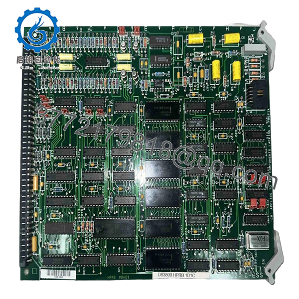
The GE DS3800HPRB1D1C is a fundamental safety module within the Mark IV Speedtronic control architecture. Known as the HPRB board, it acts as the physical interface between the system’s digital logic and the turbine’s emergency trip solenoids and master control relays. When the control system detects a critical fault, this board executes the physical “break” in the circuit to safely shut down the turbine.
From a supply chain perspective, the HPRB board represents a “Single Point of Failure” risk. Because it uses electromechanical relays, it is subject to physical wear and contact pitting over time. We strongly advise against using refurbished HPRB boards in critical protection circuits; a relay that sticks or fails to transition can lead to a failure-to-trip scenario. By securing a New Surplus unit, you ensure that the relay contacts have zero carbon buildup and the return springs are at factory tension, maintaining the integrity of your plant’s safety instrumented system (SIS).

- DS3800HPRB1D1C
- DS3800HPRB1D1C
5. Installation & Configuration Guide
Stage 1: Pre-Installation (Prep & Safety)
Ensure the turbine is completely shut down and all power to the Mark IV rack is isolated. Wear a grounded ESD wrist strap. Use a permanent marker or camera to document the orientation of any existing jumpers or wiring leads connected to the front of the board.
Stage 2: Removal
Unlock the card cage ejector tabs. Carefully pull the DS3800HPRB1D1C straight out of its slot. Inspect the backplane connector for any signs of arcing or dust buildup. Place the old board in an ESD-shielded bag immediately.
Stage 3: Installation (Clone & Seat)
Verify that the jumper settings on the new DS3800HPRB1D1C match the original board exactly. Align the board with the card guides and push firmly until the edge connector is fully seated in the backplane. Lock the ejector tabs to ensure the board cannot vibrate loose during operation.
Stage 4: Power-On & Testing
Power up the Mark IV rack and perform a “Relay Test” sequence if supported by your operator interface. Verify that each relay on the HPRB clicks audibly and the corresponding LED illuminates. Ensure there are no “Diagnostic Alarm” messages related to the protection string before attempting a turbine start.
6. Firmware/Software Versions & Upgrade Notes
- Revision Control: The ‘G1D1C’ revision is specific to certain Mark IV builds. Ensure your technical documentation supports this revision, as subtle changes in relay timing or coil resistance can occur between older ‘G1’ and newer ‘G1D1C’ versions.
- Coil Voltage: This board is designed for specific internal bus voltages. Verify that your power supply modules are providing stable 24V or 125V DC (depending on site configuration) to ensure reliable relay pull-in.
- No Software Load: This is a hardware-driven board; it does not require a software download, but the system must be rebooted to recognize the hardware change in the I/O map.
7. Frequently Asked Questions (FAQ)
What is the most common cause of failure for the HPRB board?
The most common failures are coil burnout or contact welding due to excessive switching cycles or electrical surges in the trip string. Since these are physical components, they have a finite cycle life.
Are the relays on this board replaceable?
While the relays are soldered to the PCB, we do not recommend field repairs. Desoldering components on these multi-layer boards can damage internal traces. Replacing the entire board with a New Surplus unit is the only way to guarantee OEM-level safety.
How do I verify if a relay on this board is stuck?
The on-board LEDs provide a visual cue of the logic state, but a multimeter check across the backplane pins (with the board removed) or at the terminal block is required to verify physical contact continuity.
Why is “New Surplus” critical for this specific board?
Because this is a protection board, reliability is a safety issue, not just an operational one. A refurbished board may have relays that are near the end of their mechanical life. New Surplus gives you a 100% reliable life cycle.
Can this board be used in any slot of the Mark IV?
No, it must be placed in the specific slots designated for protection/relay logic (typically in the , , or cores) as defined by your system’s hardware configuration.



