
 WhatsApp: +86 16626708626
 Email:
  Phone: +86 16626708626
Description
3. Key Technical Specifications
| Parameter | Value |
|---|---|
| Manufacturer | General Electric |
| Model Number | DS3800HSCD |
| Product Series | Speedtronic Mark IV DS3800 |
| Board Type | High-Level Non-Isolated Input Board |
| Application | Turbine control signal acquisition |
| Input Style | High-level non-isolated signal interface |
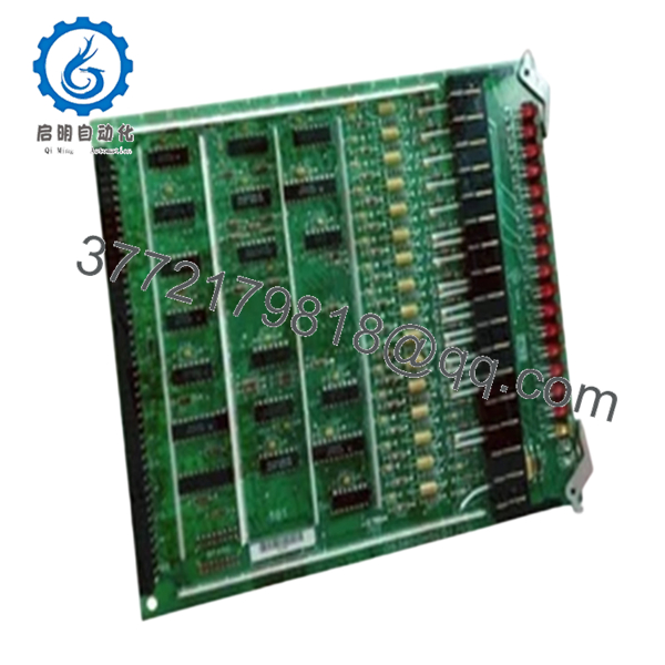
| LED Indicators | 16 red LEDs, 1 amber LED |
| Memory Support | EEPROM module socket |
| Adjustable Components | 3 onboard trimmer resistors |
| Logic Components | TTL integrated circuits |
| Connector Type | Modular edge connector |
| Retention System | Dual retention levers |
| Mounting Method | Rack-mounted PCB |
| PCB Coating | Industrial conformal coating |
| System Compatibility | GE Mark IV turbine control cabinets |
| Handling Requirement | ESD-safe handling mandatory |
The GE DS3800HSCD is a High-Level Non-Isolated Input Board designed for GE Mark IV Speedtronic turbine control systems. The board processes high-level field input signals and provides diagnostic indication through onboard LEDs.
4. Product Introduction
The GE DS3800HSCD is a High-Level Non-Isolated Input Board used within GE Speedtronic Mark IV turbine control systems. The board handles high-level signal acquisition and monitoring functions for turbine control and associated drive subsystems.
In field deployments, these boards are commonly retained as operational spares because failed input processing hardware can create nuisance trips, startup inhibits, or unstable signal interpretation during turbine operation. Most facilities still running Mark IV hardware prefer direct board replacement rather than a complete controls migration during outage windows.
5. Installation & Configuration Guide
Stage 1: Pre-Installation Preparation (Estimated Time: 10–15 Minutes)
⚠️ Safety First
- Notify operations before shutdown.
- Verify turbine safe-state condition.
- Apply lock out/tag out procedures.
- Wait at least 5 minutes for cabinet capacitor discharge.
- Verify zero voltage using a calibrated Fluke 115 multimeter.
These boards often sit inside cabinets carrying high-voltage drive circuitry nearby. Never trust panel indicators alone. Verify voltage physically.
Tools Required
- Grounded ESD wrist strap
- PH1 screwdriver
- Fluke 115 multimeter
- Smartphone for documentation photos
- Wire labels
- ESD-safe work mat
- Flashlight for cabinet inspection
Data Backup
- Record cabinet slot location.
- Photograph:
- Connector orientation
- Retention lever position
- Grounding straps
- Adjacent board locations
- Document trimmer resistor positions before touching them.
- Record any EEPROM module identifiers.
⚠️ The EEPROM module matters. I’ve seen techs transfer the wrong EEPROM from another spare board and spend hours chasing phantom startup faults.
Stage 2: Removing the Old Module (Estimated Time: 5–10 Minutes)
- Remove cabinet access cover.
- Label and disconnect associated wiring carefully.
- Release retention levers evenly.
- Remove mounting hardware if present.
- Pull the board straight outward to avoid connector damage.
- Inspect:
- Bent pins
- Connector oxidation
- Heat discoloration
- Dust contamination
- Cracked solder joints
⚠️ Important: Keep the original board nearby until the replacement passes full operational testing.
I’ve watched maintenance crews discard old boards too quickly, only to realize the replacement shipped with different EEPROM contents or jumper behavior.
Stage 3: Installing the New Module (Estimated Time: 10 Minutes)
- Wear the grounded ESD strap before touching the board.
- Verify exact model:
- DS3800HSCD
- Compare all revision markings and EEPROM configuration.
Configuration Clone (Crucial)
Replicate:
- EEPROM module placement
- Trimmer resistor settings
- Connector orientation
- Grounding arrangement
⚠️ This is one of the most common startup mistakes on older Mark IV systems. A mismatched EEPROM or incorrect trimmer setting can create unstable signal readings immediately.
- Insert the board evenly into rack guides.
- Lock retention levers fully.
- Reconnect all cables carefully.
Self-Checklist
- Model numbers match
- EEPROM verified
- Trimmer settings documented
- Connectors fully seated
- Retention levers locked
- Grounding verified
Stage 4: Power-On & Testing (Estimated Time: 15–20 Minutes)
Pre-Power Check
- Verify no short exists on the 24 V rail.
- Confirm cabinet grounding continuity.
- Inspect connector seating carefully.
Power-On Sequence
- Energize the control rack first.
- Observe LED startup behavior.
- Verify communication with the Mark IV controller.
- Monitor input signal activity using onboard LEDs.
- Connect engineering workstation if available.
- Perform dry-run testing before enabling field operation.
Functional Verification
Check:
- Stable input signal processing
- Proper LED activity
- No watchdog alarms
- No intermittent input faults
- Stable communication behavior
The onboard LEDs provide useful real-time diagnostics. The 16 red LEDs illuminate during active signal processing, while the amber LED indicates board status conditions.
⚠️ Troubleshooting Note
If unstable input behavior appears after replacement:
- First suspect EEPROM mismatch.
- Second inspect connector seating.
- Third verify trimmer resistor settings.
I once watched a startup crew chase intermittent turbine input alarms for nearly an entire shift. Turned out the replacement board shipped with a mismatched EEPROM module from another Mark IV assembly.
Technical Pitfall & Survival Guide
❗ Firmware and EEPROM Mismatch
EEPROM contents can affect startup behavior and signal handling.
Avoidance:
Document EEPROM identifiers before removal and verify compatibility before installation.
I’ve seen otherwise healthy boards fail initialization because the EEPROM data did not match the cabinet configuration.
❗ Trimmer Resistor Misadjustment
This board includes 3 onboard trimmer resistors for calibration.
Avoidance:
Photograph original positions before adjustment.
A careless adjustment can destabilize input scaling immediately.
❗ Connector Seating Problems
The modular edge connector must seat evenly.
Avoidance:
Insert the board straight and lock retention levers fully.
A partially seated connector creates intermittent faults that are miserable to troubleshoot during startup.
❗ Non-Isolated Input Risks
This board processes non-isolated high-level signals.
Avoidance:
Verify grounding and shielding carefully before energizing the cabinet.
Noise coupling problems on older cabinets are more common than people admit.
❗ Electrostatic Discharge (ESD)
TTL logic devices and EEPROM modules are highly sensitive to static discharge.
Avoidance:
Use grounded wrist straps and ESD-safe surfaces at all times.
I once watched a technician unpack a replacement board on ordinary cardboard during winter. The board booted initially, then failed after twenty minutes of runtime. Static damage. Expensive lesson.
Keep these checks in mind and you’ll save yourself 90% of typical rework time.
- DS3800HSCD
6. Frequently Asked Questions (FAQ)
Q1: Can I hot-swap the DS3800HSCD?
No.
The GE Mark IV platform was not designed for live insertion of input boards. Hot-swapping can damage the backplane, corrupt signal processing, or trigger turbine trips.
Always power the cabinet down completely first.
Q2: Is the DS3800HSCD obsolete?
Yes.
This board belongs to the GE Mark IV legacy platform. Most available inventory today comes from:
- New surplus stock
- Plant spare inventories
- Professionally refurbished units
Factory-sealed inventory still exists but quantities are increasingly limited globally.
Q3: What does “non-isolated input board” mean?
It means the board processes high-level field signals without galvanic isolation between certain circuitry sections.
Because of that, grounding quality and shielding become extremely important during installation.
Noise issues can create intermittent faults that look like controller failures.
Q4: What are the onboard LEDs used for?
The board includes:
- 16 red diagnostic LEDs
- 1 amber status LED
The red LEDs indicate active circuit behavior and signal processing states. They are extremely useful during field troubleshooting.
Q5: Will replacing this board erase turbine logic?
Usually no.
Primary turbine application logic normally resides in the Mark IV processor architecture, not directly on this input board.
However, EEPROM configuration and calibration settings still matter greatly.
Q6: Why are some units much cheaper than others?
Usually because of:
- Unknown test status
- Missing EEPROM verification
- Cosmetic damage
- Untested pull inventory
- Refurbished boards sold unclearly
Always request:
- Serial photos
- EEPROM photos
- Runtime test reports
- Connector close-up photos
- Packaging verification
A serious supplier should provide them without hesitation.
Q7: What testing should a supplier perform before shipment?
Minimum acceptable QC should include:
- Visual PCB inspection
- Connector integrity inspection
- LED startup verification
- EEPROM verification
- Insulation resistance testing (>10 MΩ preferred)
- 24-hour runtime testing
- ESD-safe packaging and sealing
Good suppliers should also provide:
- QC photos
- Runtime verification reports
- Test videos
- Packaging photos before shipment
A board tested under live Mark IV rack conditions means substantially more than a simple “power-on tested” label.


